Connection box with charging fluid supply arrangement for an internal combustion engine

a charging fluid and internal combustion engine technology, applied in the direction of engine operation, non-fuel substance addition to fuel, exhaust gas recirculation, etc., can solve the problems of increasing the flow resistance of the charging fluid, occupying a large space, so as to achieve a long and efficient mixing path

Active Publication Date: 2012-12-27
ROLLS ROYCE SOLUTIONS GMBH
View PDF0 Cites 8 Cited by
  • Summary
  • Abstract
  • Description
  • Claims
  • Application Information

AI Technical Summary

Benefits of technology

[0021]In this way, the mixing section can advantageously be sufficiently long for achieving a good mixing of the exhaust gas and the charge air. On the other hand, this is achieved without construction space disadvantages, since the mixing section extends along the longitudinal extension of the charging fluid duct, for example thereabove. The mixing section can be accommodated there in a particularly compact manner and facilitates a particularly efficient and good mixing of the charge air and the exhaust gas.
[0043]An additional lower connection box preferably includes a bottom side connecting flange for its installation above the crankcase of the internal combustion engine. The additional lower connection box can be mounted advantageously directly to the crankcase. Preferably, the housing of the lower connection box includes a lower opening. This opening is specifically arranged in the cross-section of the lower side connecting flange. It can advantageously be utilized to form with the crankcase a bottom housing wall in the opening cross-section of the lower connection box. The lower connection box can use the crankcase of the internal combustion engine to form a charge air guide structure up to the first mixing section point thereby saving material. An additional upper connection box may also be provided which may also form a cover for the connection box below.

Problems solved by technology

Because of the high- and / or low pressure charge air flows and the exhaust gas recirculation flows the establishment of a charging arrangement however may be quite space consuming.
This basically reasonable arrangement however is comparably space-consuming and also results in an increased flow resistance of the charging fluid to be formed in the mixing chamber.
A problem encountered with this arrangement however is that the mixing area in the direction of the manifold is relatively short since it extends essentially transverse to the longitudinal side of an engine block if the sideward extensions of the engine block cannot be excessively large.
The solution proposed in U.S. Pat. No. 5,957,116 is consequently either comparatively inefficient or it requires a large installation space.
This problem is particularly difficult in connection with small internal combustion engines, especially Diesel internal combustion engines since very little space is generally available for a relatively large mixing space in the small engine application environment.
As a result, the admixing of exhaust gas to the charge air as proposed by U.S. Pat. No. 5,957,117 is either comparatively space consuming or ineffective.

Method used


Image

  • Connection box with charging fluid supply arrangement for an internal combustion engine
  • Connection box with charging fluid supply arrangement for an internal combustion engine
  • Connection box with charging fluid supply arrangement for an internal combustion engine

Examples


Embodiment Construction

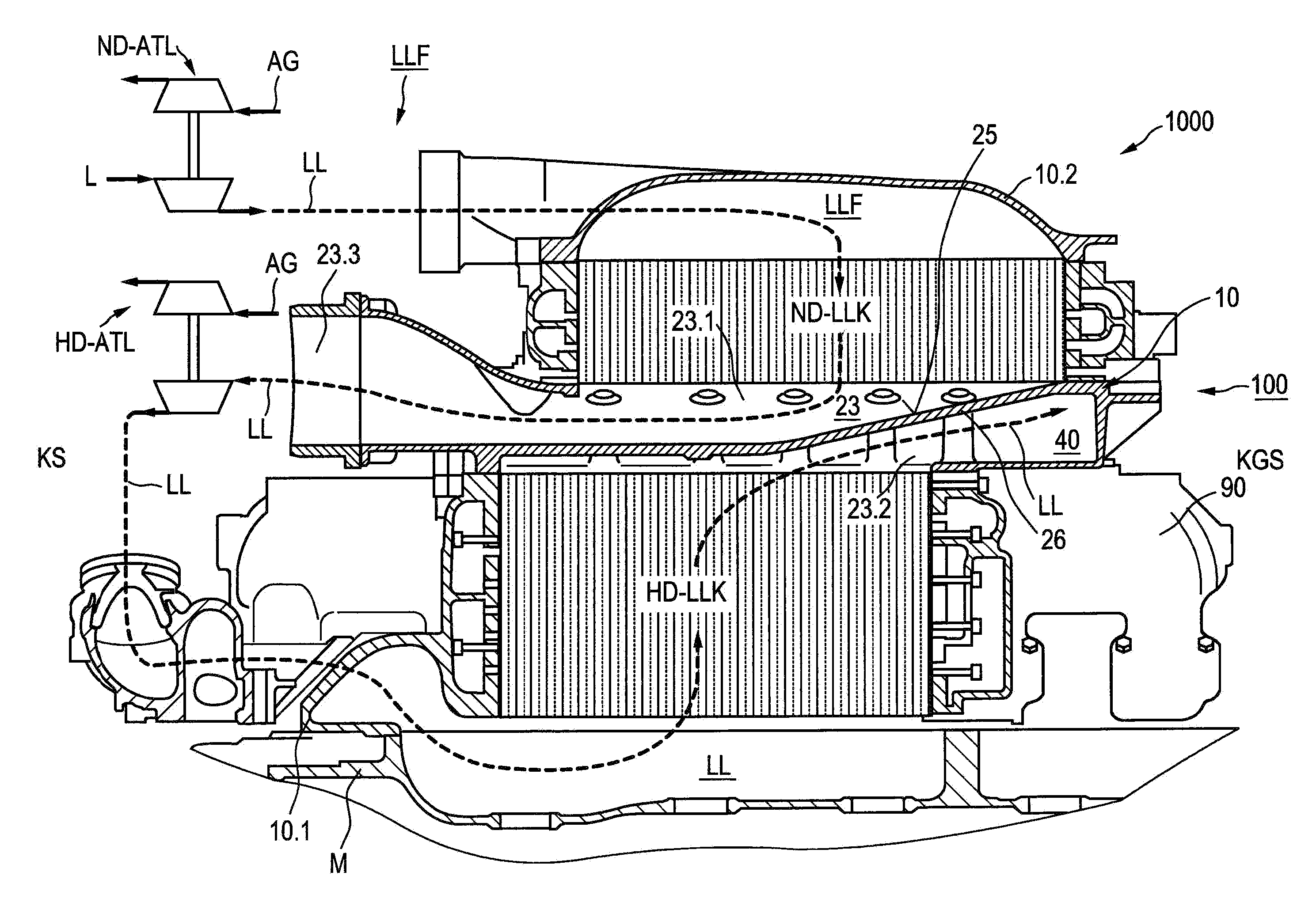
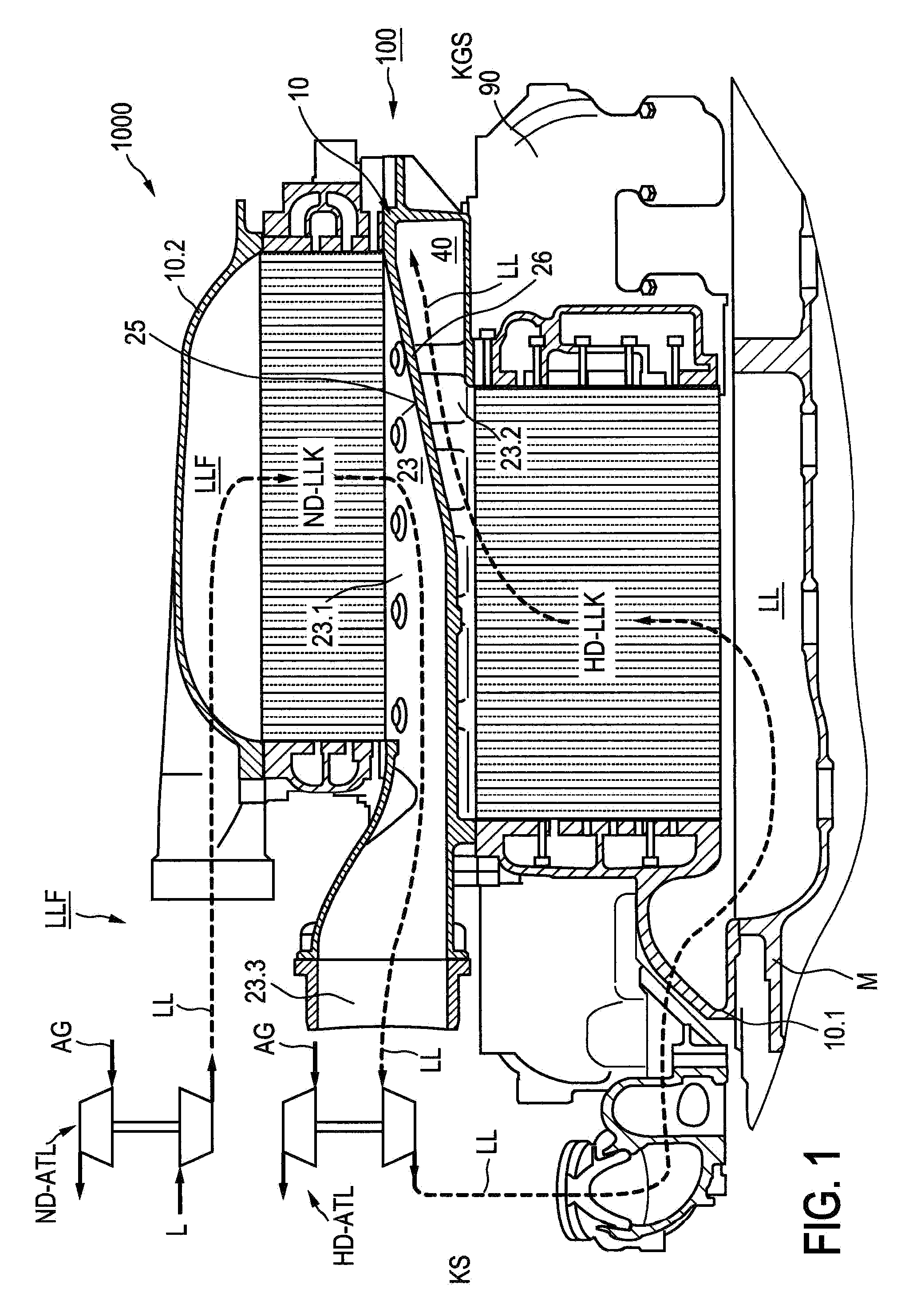
[0051]FIG. 1 shows an internal combustion engine 1000 with a motor block M and two-stage charging by means of a low pressure exhaust gas turbocharger ND-ATL and a high-pressure exhaust gas turbocharger HD-ATL. Fresh air L is compressed in the low pressure exhaust gas turbocharger ND-ATL by a low-pressure compressor LL and supplied to the charge air line LLF. In the charge air line LLF, a low pressure charge air cooler ND-LLK is arranged in which the compressed charge air LL is cooled and then supplied to a high pressure compressor of a high pressure turbocharger HD-ATL. Further, the charge air LL is then supplied to a high pressure charge air cooler HD-LLK. Finally, the charge air LL leaves the charge air guide arrangement LLF to a charge fluid supply 100 specifically to enter a charging a fluid duct 90 to which also recirculated exhaust gas is supplied. Ahead of the charging fluid duct 90 is a mixing channel 12.1, 12.2 which is described in connection with FIGS. 2-5 and which is di...


PUM


Abstract

In a connection box for direct connection to a charging fluid duct of a charging fluid supply designed for intermixing a charge air and an exhaust gas to form a charging fluid, comprising a housing with a charge air connecting space including at least a connection for a charge air guide arrangement, and at least one mixing channel in communication with the charge air connecting space via a connection for supplying charge air to the mixing channel and the mixing channel including a supply side exhaust gas connection for an exhaust gas recirculation and a charging fluid-side mixing channel connection for the charging fluid duct, the connection is arranged at a first front side of the housing, and the mixing channel extends along a longitudinal side of the housing from the first front side to a second front side of the housing opposite the first front side.

Description

BACKGROUND OF THE INVENTION[0001]The invention resides in a connection box for a charging fluid supply arrangement to an internal combustion engine with at least one connection for a charge air supply line, a mixing arrangement with exhaust gas supply connections and a mixing channel.[0002]Such a connection box is designed for a direct connection to a charging fluid line of a charging fluid supply and serves for a combination of charge air and exhaust gas to a charging fluid. It includes a housing with a charge air connecting chamber having at least one connection for a charge air supply line and at least one mixing channel in communication, via a connector charge air can be supplied to the mixing channel. The mixing channel includes a supply-side exhaust gas connection for exhaust gas recirculation and a charging fluid line-side mixing channel connection for the charge air supply line.[0003]The invention also resides in a charging fluid supply arrangement with a connection box and ...

Claims


Application Information

Patent Timeline
Patent Type & Authority Applications(United States)
IPC IPC(8): F02M25/07
CPCF02B29/0412F02B29/0431F02B29/0462F02B29/0475Y02T10/146F02M35/10222F02M35/116Y02T10/121F02M25/0722F02M26/19F02M26/00F02M26/22Y02T10/12
Inventor BAUMANN, HERMANNSEIDERER, DOMINIKGAUSS, WALTER
Owner ROLLS ROYCE SOLUTIONS GMBH
Why Eureka
Try Eureka