High efficiency thermal management system

a thermal management system and high efficiency technology, applied in the field of high efficiency thermal management system, can solve the problems of inherently limited system performance and efficiency, high cost, and inability to meet the needs of large volume of air flow, so as to achieve optimum fluid flow and heat transfer, improve temperature uniformity, and improve the effect of cooling efficiency

Inactive Publication Date: 2012-12-27
WISCONSIN ALUMNI RES FOUND
View PDF5 Cites 25 Cited by
  • Summary
  • Abstract
  • Description
  • Claims
  • Application Information

AI Technical Summary

Benefits of technology

[0027]The apparatuses and methods described herein provide many advantages over conventional cooling systems. The jet array employed in the present two-phase impingement system removes more thermal energy per unit of fluid flow and temperature difference than a single-phase impingement system. The two-phase system also maintains temperature uniformity better than a single-phase cooling system due to the phase change behavior. The non-perpendicularly angled tubular nozzles that impinge coolant streams non-perpendicularly on a surface offer optimum fluid flow and heat transfer compared with other heat transfer technologies, provide for more efficient use of coolant compared with perpendicularly oriented jet nozzles, allow for a more compact pack...

Problems solved by technology

Maintaining such a temperature range is a challenging problem that is only increasing in importance and difficulty as semiconductor technology continues to progress.
However, these systems are inherently limited in terms of their performance and efficiency.
Due to the very low volumetric heat capacity of air, a large volume of air flow is required to remove the heat load of even one processor.
Furthermore, air-cooled systems are not only inefficient in themselves but also cause the electronics they cool to operate less efficiently.
However, the intervening materials between the water and the work piece induce significant thermal resistance, which reduces the efficiency of the system.
In addition to the thermal resistance, the intervening materials add to the cost and time of manufacture, constitute additional points of failure, and provide possible disposal issues.
Finally, the intervening materials render the system unable to efficiently deal with local hot spots on a work piece.
However, the dielectric coolants are less efficient coolants t...

Method used


Image

  • High efficiency thermal management system
  • High efficiency thermal management system
  • High efficiency thermal management system

Examples


example

[0076]Many impingement technologies exist, but few have shown commercial promise and none have gained wide-scale commercial acceptance to date due to generally high flow rate requirements and limitations on scalability.

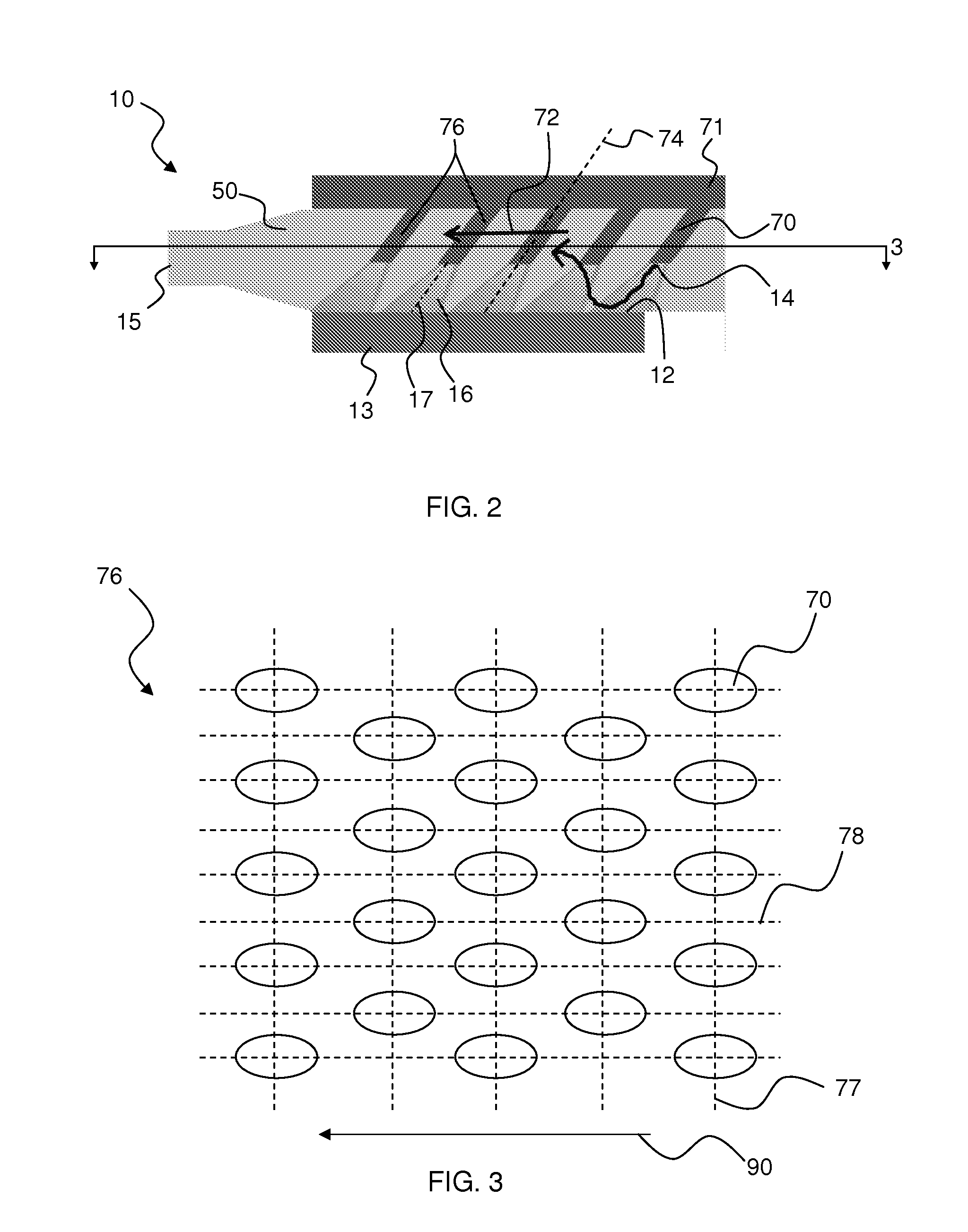
[0077]An improved impinging jet array apparatus has been developed and described herein. As described above, the current work has identified that angling the tubular nozzles and impinging the stream at a non-perpendicular angle with respect to the surface significantly improves the scalability of arrays of jets.

[0078]In addition, laboratory tests have demonstrated that two-phase impinging jets can perform 80% to 100% better than single-phase jets with the same flow rate. A chamber comprising a tubular nozzle configured to project a jet impinging on a work piece surface was configured. The pressure in the chamber was set to establish a saturation temperature of either 95° C. (FIG. 5A) or 74° C. (FIG. 5B). The latter saturation temperature (74° C.) was chosen to substan...


PUM


Abstract

Disclosed are methods and apparatuses for cooling a work piece surface using two-phase impingement, such as direct jet impingement. Preferred methods include flowing a coolant through a chamber comprising a surface to be cooled by projecting a jet stream of coolant against the surface while maintaining pressure in the chamber to permit at least a portion of coolant contacting the surface to boil. Preferred apparatuses include a chamber comprising the surface and tubular nozzles configured to project a stream of coolant against the surface, a pump for forcing coolant through the tubular nozzles, a pressurizer for maintaining an appropriate pressure in the chamber, and a heat exchanger for cooling the coolant exiting the chamber. The apparatuses may further include a pressure regulator for detecting changes in temperature of the coolant exiting the chamber and communicating with the pressurizer to adjust the maintained pressure accordingly. The methods and apparatuses disclosed herein provide for effective and efficient cooling of work piece surfaces.

Description

STATEMENT REGARDING FEDERALLY SPONSORED RESEARCH[0001]This invention was made with government support under N00014-09-D-0738 awarded by the NAVY / ONR. The government has certain rights in the invention.FIELD OF THE INVENTION[0002]The present invention is directed to methods and apparatuses for cooling work pieces such as processors or other electronic devices.BACKGROUND[0003]Methods for maintaining electronic devices within a safe and desirable operating temperature range have been a topic of research since the invention of the transistor.[0004]Maintaining such a temperature range is a challenging problem that is only increasing in importance and difficulty as semiconductor technology continues to progress. State of the art microprocessors easily produce more than 40 W of thermal energy per square centimeter of the microchip surface. Power electronics can attain heat densities three times this level.[0005]In addition to the requirement to manage such high heat intensity, there is a n...

Claims


Application Information

Patent Timeline
IPC IPC(8): F28D15/00
CPCH01L23/427H01L23/4735H01L2924/0002H01L2924/00F28C3/08F28D15/00
Inventor SHEDD, TIMOTHY A.
Owner WISCONSIN ALUMNI RES FOUND
Why Eureka
Try Eureka