Wireless communication module and wireless communication device

a wireless communication module and wireless communication technology, applied in the direction of loop antennas, solid-state devices, instruments, etc., can solve the problems of very low possibility of multi-layer substrate being detached from the base substrate, and achieve the effect of significantly reducing the possibility of the wireless ic chip being detached, and reducing the height of the wireless communication modul

Inactive Publication Date: 2012-12-27
MURATA MFG CO LTD
View PDF6 Cites 111 Cited by
  • Summary
  • Abstract
  • Description
  • Claims
  • Application Information

AI Technical Summary

Benefits of technology

[0007]To overcome the problems described above, preferred embodiments of the present invention provide a wireless communication module and a wireless communication device that are less likely to be detached even when attached to a flexible base substrate and that have a reduced height.
[0010]With regard to the wireless communication module, because the wireless IC chip is arranged in the cavity provided in the flexible multilayer substrate including the stacked flexible base materials and the cavity is filled with the sealant, which is harder than the flexible base materials, so as to cover the wireless IC chip, the wireless IC chip is protected by the sealant. Therefore, even when an external force is applied to the flexible multilayer substrate and the multilayer substrate warps or bends, stress is less likely to be applied to the wireless IC chip. Also, because the multilayer substrate is flexible itself, when the multilayer substrate is attached to a flexible base substrate, the multilayer substrate warps or bends in accordance with the base substrate. Thus, the possibility of the multilayer substrate being detached from the base substrate is very low. Further, because the wireless IC chip is accommodated in the cavity of the flexible multilayer substrate, the height of the wireless communication module is reduced.
[0011]According to various preferred embodiments of the present invention, even when attached to a flexible base substrate, the possibility of the wireless IC chip being detached is very low, the height wireless communication module is significantly reduced.

Problems solved by technology

Thus, the possibility of the multilayer substrate being detached from the base substrate is very low.

Method used


Image

  • Wireless communication module and wireless communication device
  • Wireless communication module and wireless communication device
  • Wireless communication module and wireless communication device

Examples


first preferred embodiment

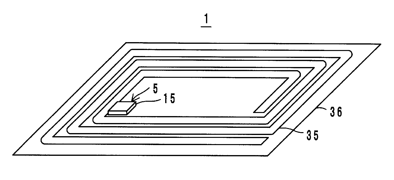
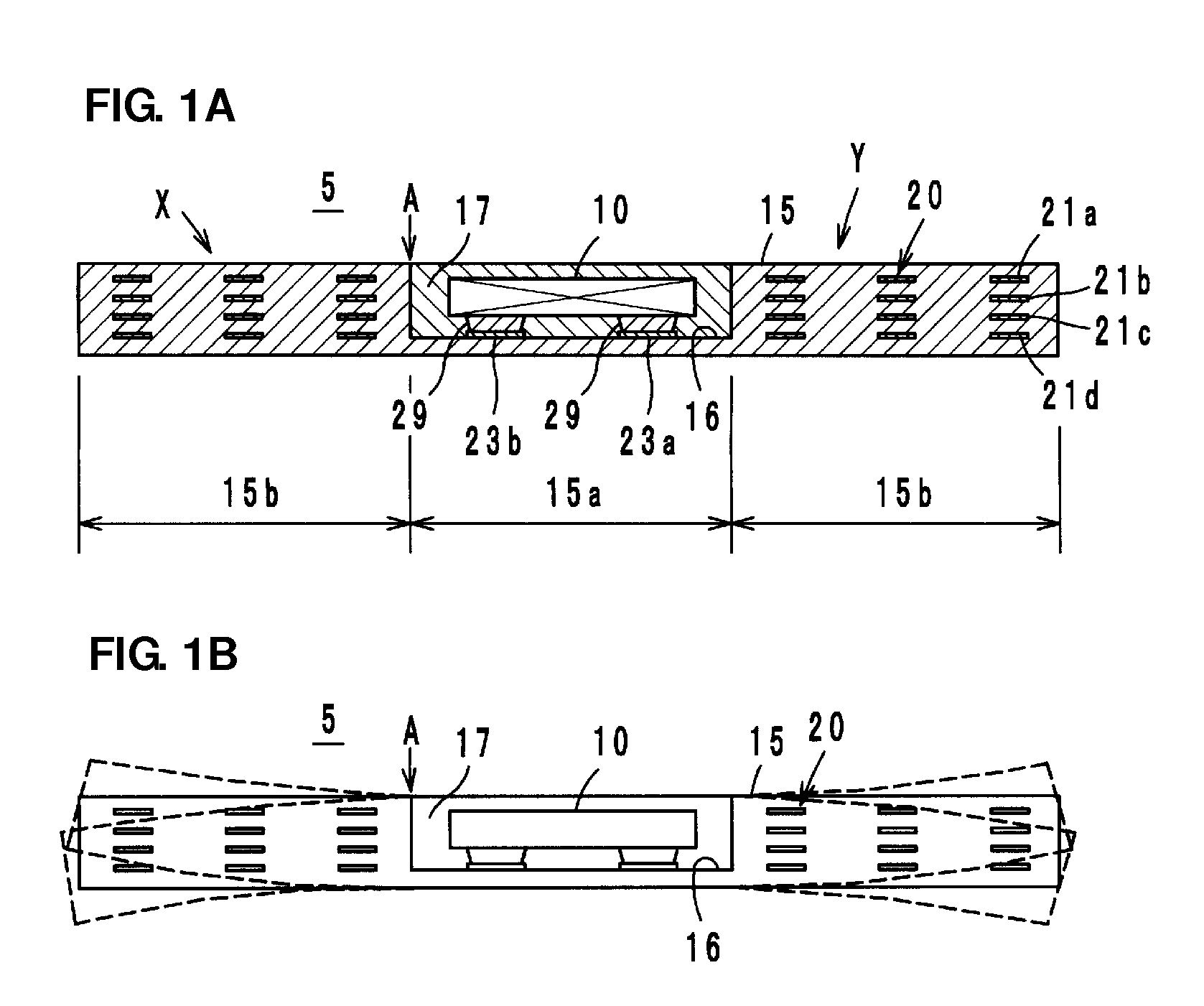
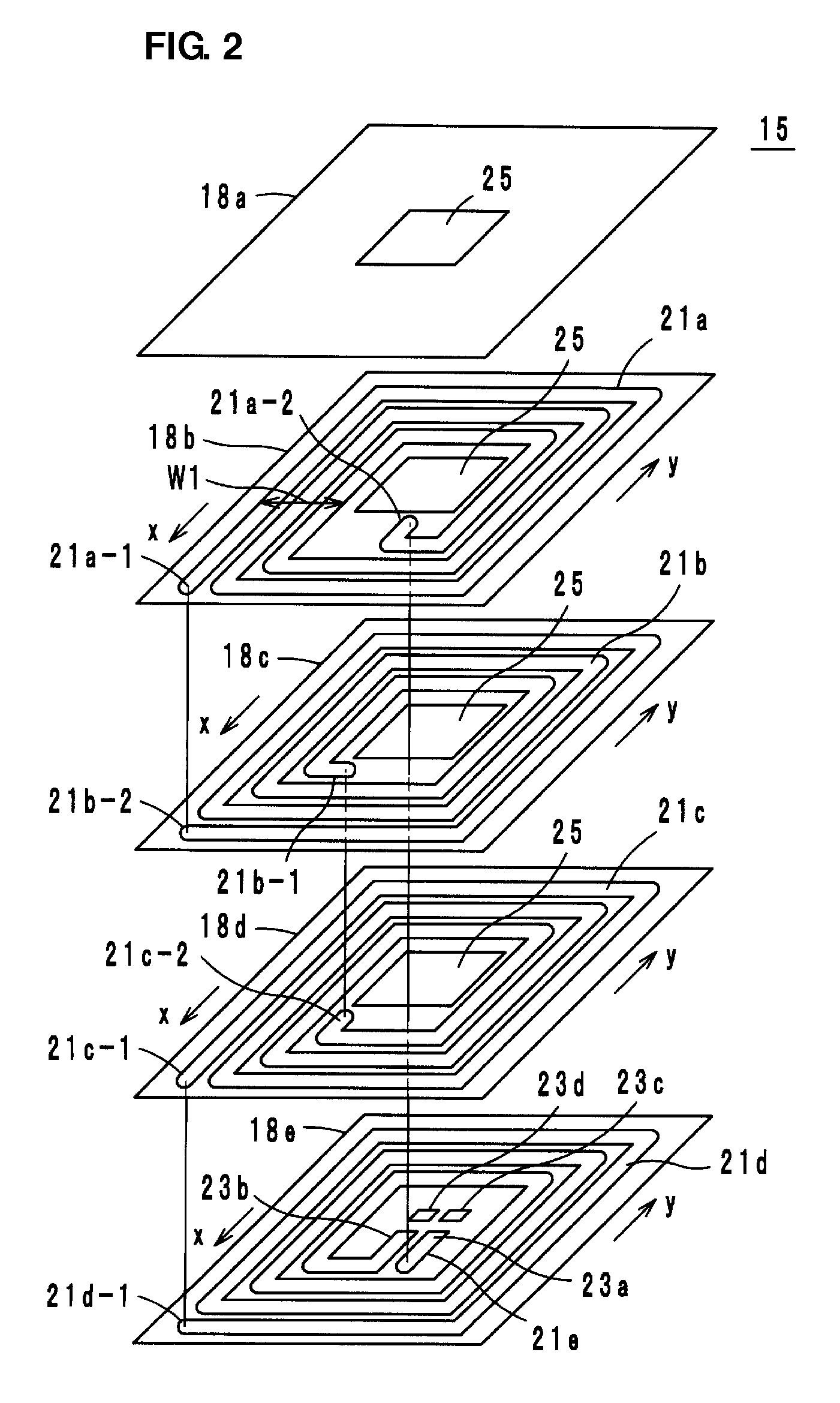
[0033]As shown in FIG. 1A, a wireless communication module 5 according to a first preferred embodiment of the present invention is preferably used in the 13.56-MHz band, for example. The wireless communication module 5 includes a wireless IC chip 10 that processes wireless signals, and a power feeding circuit substrate 15 that includes a loop-shaped electrode 20 that is electrically connected to the wireless IC chip 10 and that includes winding coil patterns 21a to 21d having a certain width W1 (see FIG. 2). The wireless IC chip 10 includes a clock circuit, a logic circuit, and a memory circuit, and necessary information is memorized in the wireless IC chip 10. With regard to the wireless IC chip 10, an input terminal electrode and an output terminal electrode provided on the back surface of the wireless IC chip 10 are electrically connected to two ends of the loop-shaped electrode 20.

[0034]The power feeding circuit substrate 15 is preferably a flexible multilayer substrate, for exa...

second preferred embodiment

[0051]As shown in FIG. 5, a wireless communication module 5A according to a second preferred embodiment of the present invention is formed by disposing the wireless IC chip 10 in the cavity 16 of the power feeding circuit substrate 15, connecting the wireless IC chip 10 to the lands 23a and 23b, fixing the wireless IC chip 10 with a sealant 17a preferably made of an underfill resin, for example, and then sealing the cavity 16 with the sealant 17 preferably made of a harder resin, for example. For example, an epoxy resin can preferably be used as the sealant 17a made of an underfill resin. Stress that occurs between the substrate 15 and the sealant 17 is dispersed by setting the hardness of the sealant 17a to an intermediate level between that of the power feeding circuit substrate 15 and that of the sealant 17, which results in improved joint reliability.

Third and Fourth Preferred Embodiments

[0052]The coil patterns 21a to 21d defining the loop-shaped electrode 20 are made of a condu...

fifth preferred embodiment

[0055]In a wireless communication module 5d according to a fifth preferred embodiment of the present invention shown in FIG. 8, the coil patterns 21a to 21d provided on adjacent layers are arranged so as not to overlap one another when viewed in plan. If coil patterns that are vertically adjacent to each other overlap when viewed in plan, the distance between the vertically adjacent coil patterns is reduced when the power feeding circuit substrate 15 warps or bends, resulting in fluctuations (increase) of the line capacity and of the resonant frequency of the LC resonant circuit defined by the loop-shaped electrode 20. However, according to the fifth preferred embodiment, fluctuations of the line capacity (eventually the resonant frequency) due to warping or bending of the substrate 15 are minimized or prevented because vertically adjacent coil patterns do not overlap each other when viewed in plan.

Second Example of Wireless Communication Device

[0056]Next, a second example of a wire...


PUM


Abstract

A wireless communication module and a wireless communication device that are less likely to become detached even when attached to a flexible base substrate and have a reduced height includes a flexible multilayer substrate including a plurality of stacked flexible base materials and a cavity provided therein, a wireless IC chip arranged in the cavity, and a sealant filled in the cavity so as to cover the wireless IC chip. The sealant is a material that is harder than the flexible base materials. The flexible multilayer substrate includes a loop-shaped electrode defined by coil patterns. The loop-shaped electrode is electrically connected to the wireless IC chip.

Description

BACKGROUND OF THE INVENTION[0001]1. Field of the Invention[0002]The present invention relates to wireless communication modules and wireless communication devices, and more particularly, to a wireless communication module and a wireless communication device preferably for use in an RFID (Radio Frequency Identification) system, for example.[0003]2. Description of the Related Art[0004]In recent years, an RFID system has been used as an article information management system, which allows a reader / writer that generates an induction field and an RFID tag (also referred to as a wireless communication device) attached to an article to communicate with each other using a contactless system utilizing an electromagnetic field and to transmit certain information. The RFID tag includes a wireless IC that stores certain information and processes certain wireless signals and an antenna that sends and receives RF signals.[0005]Japanese Unexamined Patent Application Publication No. 2007-102348 desc...

Claims


Application Information

Patent Timeline
Patent Type & Authority Applications(United States)
IPC IPC(8): H01Q7/00H01Q1/24
CPCG06K19/07749H01Q7/00H01Q1/2225H01L2224/16225H01L2924/181H01L2924/00012H01Q1/2283
Inventor MURAYAMA, HIROMIKATO, NOBORU
Owner MURATA MFG CO LTD
Why Eureka
Try Eureka