

Tomogram observation apparatus, processing method, and non-transitory computer-readable storage medium
a processing method and tomogram technology, applied in the field of tomogram observation apparatus, can solve the problems of difficult to acquire tomograms corresponding to the same portion of the retina, difficult to scan the same position as that on a past image, and difficult to quantitatively follow up
- Summary
- Abstract
- Description
- Claims
- Application Information
AI Technical Summary
Benefits of technology
Problems solved by technology
Method used
Image

Examples
first embodiment
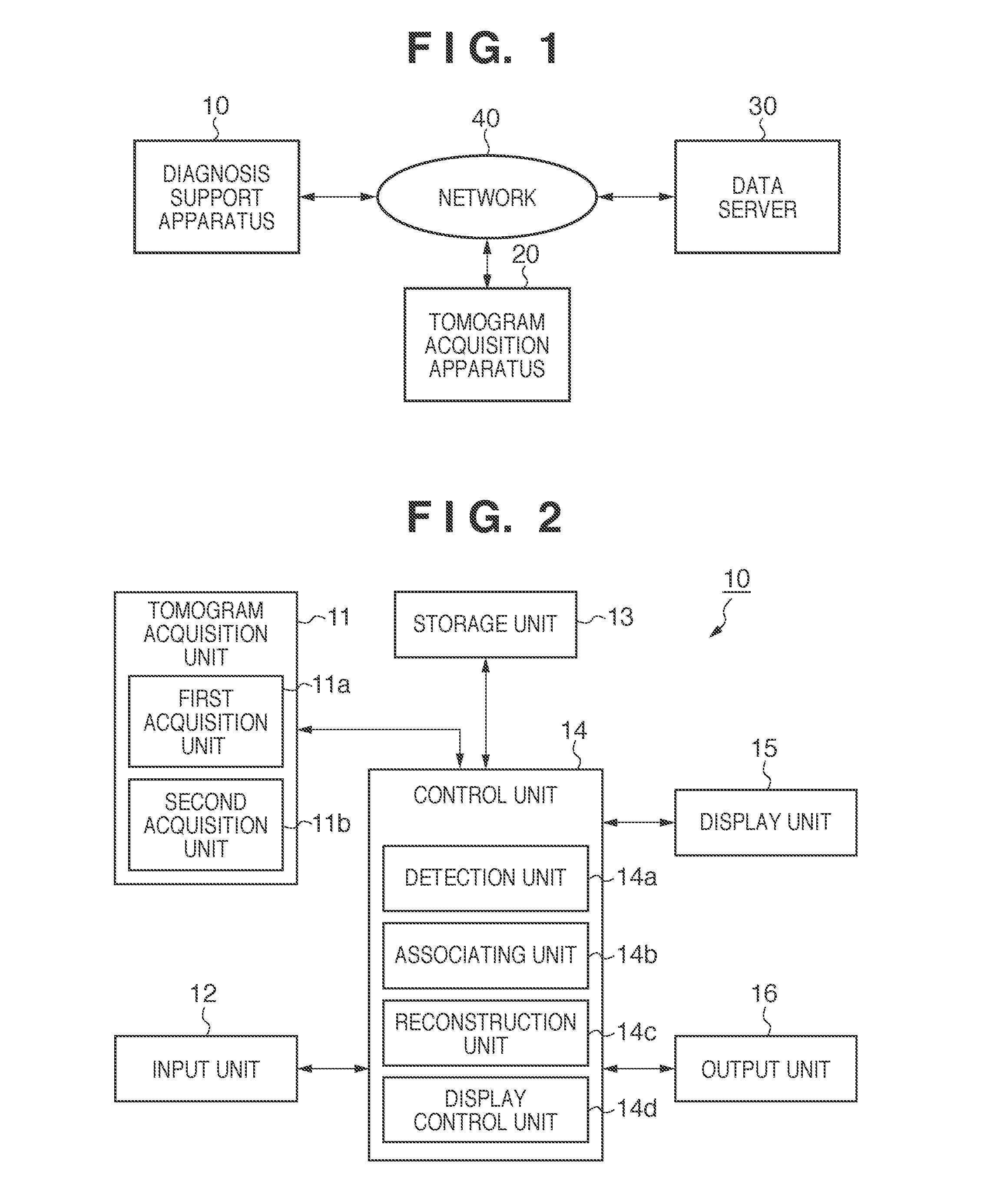
[0024]FIG. 1 is a view showing an example of the overall arrangement of a diagnosis support system according to an embodiment of the present invention. Note that this embodiment will exemplify diagnosis support for follow-up of glaucoma.
[0025]In this diagnosis support system, a diagnosis support apparatus 10, a tomogram acquisition apparatus 20, and a data server 30 are connected to each other via a network 40 formed by a LAN (Local Area Network) or the like. Note that the respective apparatuses need not always be connected to each other via the network 40 as long as they can communicate with each other. For example, they can be connected to each other via a USB (Universal Serial Bus), IEEE1394, or the like, or may be connected to each other via a WAN (Wide Area Network).
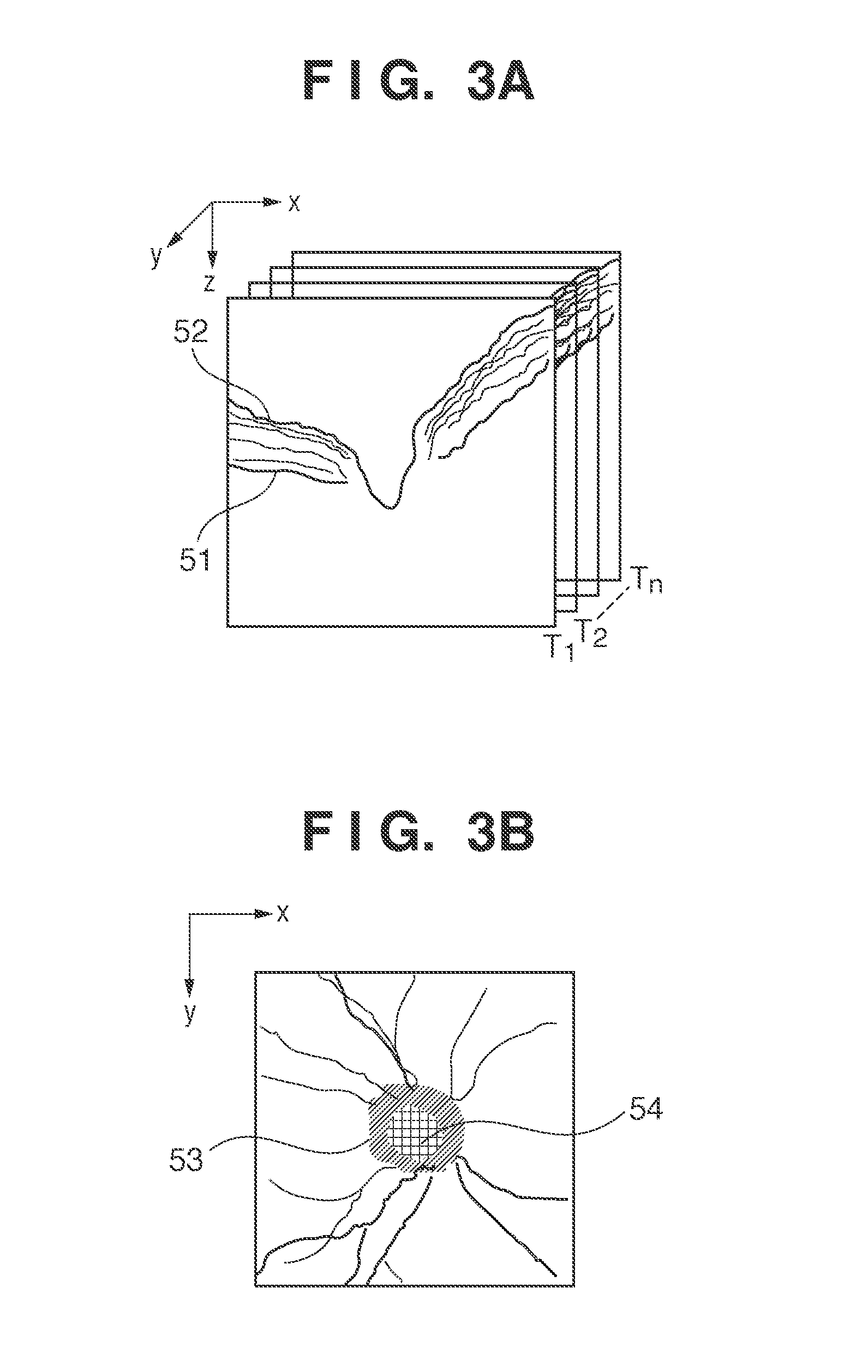
[0026]In this case, the tomogram acquisition apparatus 20 is implemented by a time-domain OCT or Fourier-domain OCT, and has a function of obtaining a tomogram showing the three-dimensional shape of the retina. The ...
second embodiment
[0082]The second embodiment will be described next. The first embodiment has exemplified the case in which images of the same eye to be examined which are captured at different times are compared in a follow-up. In contrast, the second embodiment will exemplify a case in which the left and right eyes of the same object are compared with each other. This is because the left and right eyes of the same object exhibit small variations in the sizes of the optic papillae. It is known that the sizes of the optic papillae greatly vary among individuals. In contrast, the left and right eyes of the same person exhibit small variations in the sizes of the optic papillae (it is reported that the differences in size between the left and right papillae of 99% people fall within 1 mm to 2 mm).
[0083]In this case, the second embodiment associates tomograms with each other with focus on the shapes of papilla boundaries. The second embodiment differs from the first embodiment in the association proces...
third embodiment
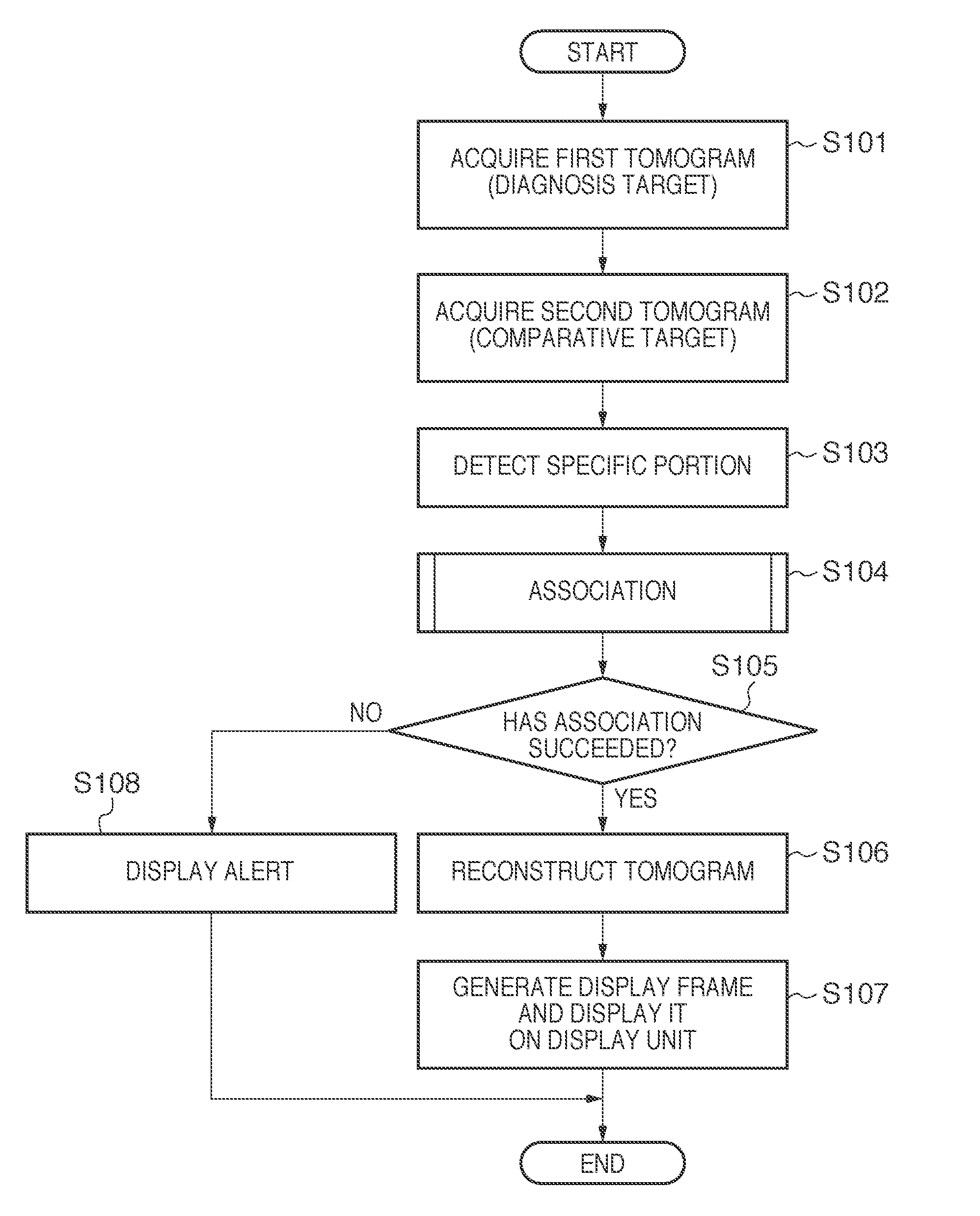
[0089]The third embodiment will be described next. The third embodiment will exemplify a case in which tomograms to be compared are processed to clarify the differences between the tomograms and present them to the operator. More specifically, when displaying tomograms to be compared, the apparatus executes difference processing to display the differences between the two tomograms to the operator. This embodiment differs from the first and second embodiments in the display control processing shown in step S107 in FIG. 4. Since the apparatus arrangement and processing other than the display control processing are the same as those in the first and second embodiments, a description of them will be omitted.
[0090]In this case, it is possible to generate a difference image by, for example, subtracting, from the luminance values of the respective pixels of the first tomogram, the luminance values of the corresponding pixels of the second tomogram. In contrast to this, it is also possible ...
PUM
 Abstract
Description
Claims
Application Information