Method of high impedance groundfault detection for differential protection of overhead transmission lines

a technology of high impedance ground fault and differential protection, which is applied in the direction of emergency protection circuit arrangements, testing circuits, instruments, etc., can solve the problems of high risk to human lives and environment, high risk of high current, and failure to protect, so as to increase the sensitivity of high resistance ground fault detection

Inactive Publication Date: 2012-12-27
ALSTOM TECH LTD +1
View PDF1 Cites 38 Cited by
  • Summary
  • Abstract
  • Description
  • Claims
  • Application Information

AI Technical Summary

Benefits of technology

[0029]With the invention method, it is possible to obtain a remarkably increased sensitivity of high resistance groundfault detection.

Problems solved by technology

Although for most cases this standard protection arrangement is sufficient, there are still cases when the protection may fail.
Such faults may not affect seriously the transmission line operation but, if uncleared, pose very high danger to human lives and environment and may develop into serious heavy current ones.
So selective detection of such faults is a problem that relates to safety of transmission lines operation.
An other example is a broken or fallen conducting primary wire which is brought into contact with the ground and thereby causes a ground fault condition.
This also means that it will be difficult to reliably separate such faults from large load changes in the network.
A consequence of this is that a high resistance fault may remain during a long period of time causing fire hazard and hazards to humans who come into contact with or in the vicinity of the conductor.
The existing methods of fault detection based on measurement of differential current are not sensitive enough to detect groundfaults via high impedance exceeding 200 Ohms.
When such a fault has occurred, a considerable change of the energy contents of these frequency current components arises.

Method used


Image

  • Method of high impedance groundfault detection for differential protection of overhead transmission lines
  • Method of high impedance groundfault detection for differential protection of overhead transmission lines
  • Method of high impedance groundfault detection for differential protection of overhead transmission lines

Examples


Embodiment Construction

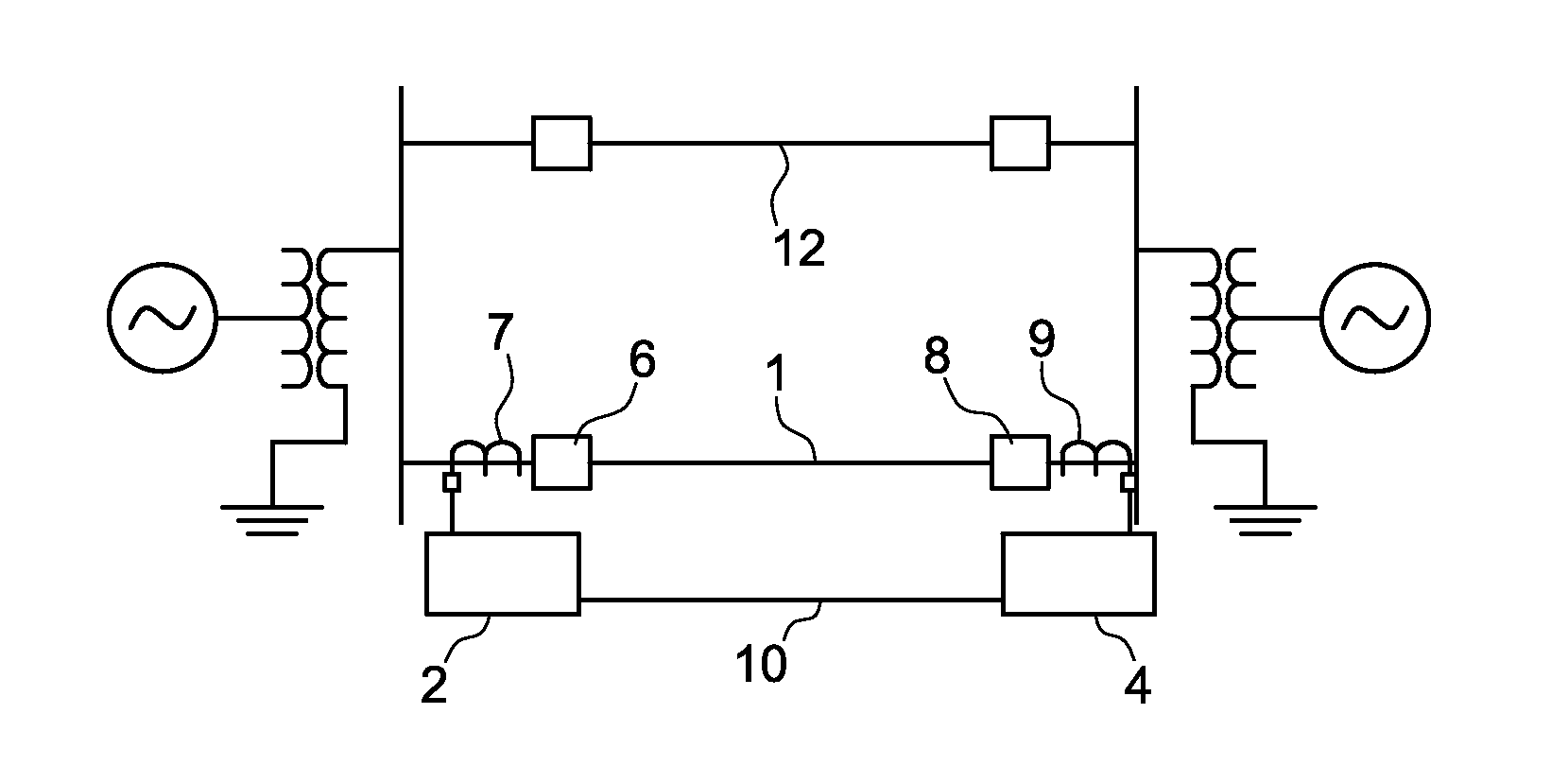
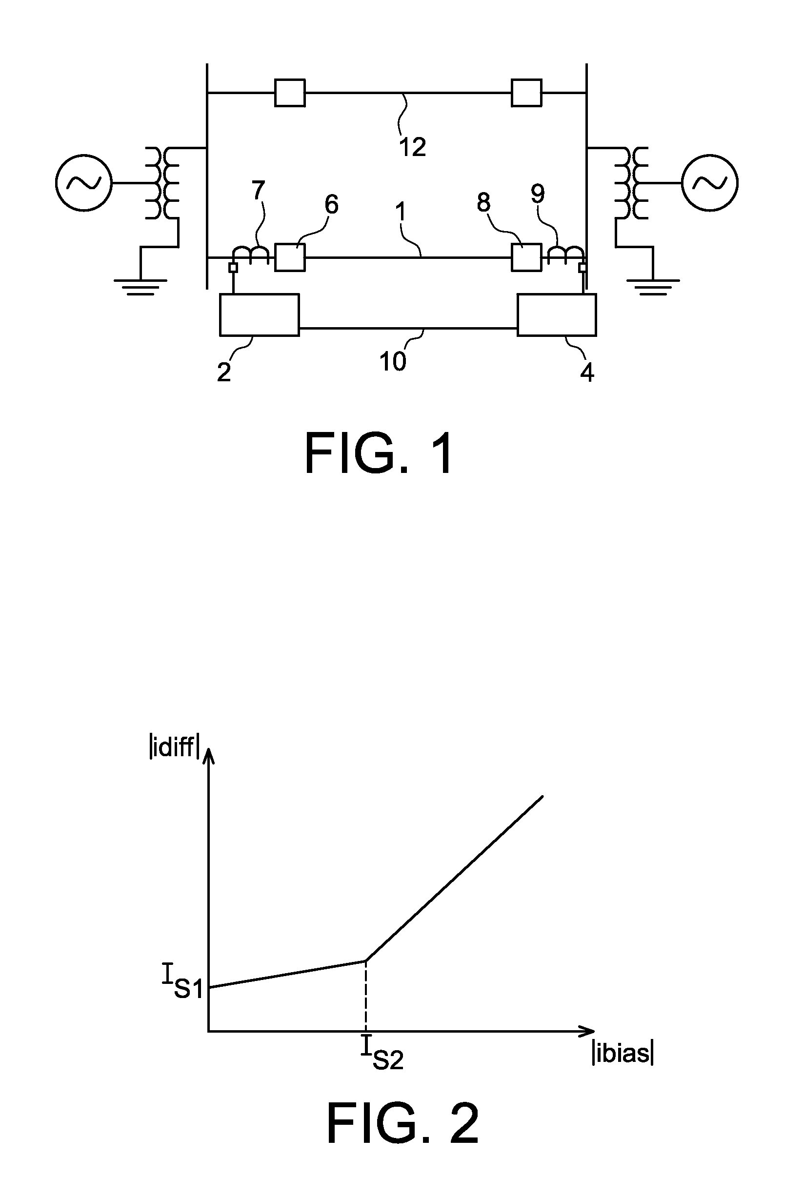
[0032]The invention method is based on determination of increment of the differential admittance, understood as the ratio of the differential current, which is the difference of phase currents flowing at both ends of a line, to phase voltage referred to the middle of a line, and calculated in faulty and in pre-fault conditions.

[0033]Such an approach ensures good compensation of phase-to-ground capacitive current. As a result sensitivity of the protection increases remarkably, thus enabling detection of groundfaults through high resistances up to 1 kOhm.

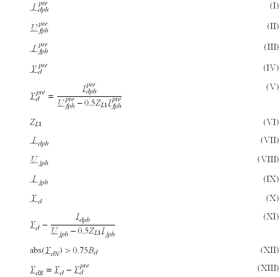
[0034]The method is based on determination of differential admittance YdR which is given by the simple formula:

YdR=Yd−Ydpre  (1)

where:

Yd: the differential admittance measured by the relay in faulty conditions

Ydpre: the differential admittance measured by the relay in pre-fault conditions.

[0035]The differential admittance Yd is determined with respect to the phase voltage in the middle of the line according to the equation:

Y_d=I_dphU_f...


PUM


Abstract

The invention concerns a method of impedance groundfault detection for differential protection of an overhead transmission line in a three-phase high voltage electric power transmission system which comprises many lines (1,12) and many protection relays (2,4), which comprises the following steps: 1) in prefault condition: —measuring the differential current (I); —measuring the phase voltage (II) at the relay location; —measuring the phase current (III) the relay location; —calculating the differential admittance (IV), with the following equation: (formula (V)). With (VI): the positive sequence impedance of the line-protected. 2) In operating condition: —measuring the differential current (VII); —measuring the phase voltage (VIII) at the relay location; —measuring the phase current (IX) at the relay location; calculating the differential admittance (X), with the following equation: (formula (XI)); —detecting a high impedance groundfault detection, if the following formula is verified: (XII) with (XIII); B0=the total line admittance.
I_dphpre(I)U_fphpre(II)I_fphpre(III)Y_dpre(IV)Y_dpre=I_dphpreU_fphpre-0.5ZL1I_fphpre(V)ZL1(VI)I_dph(VII)U_jph(VIII)I_jph(IX)Y_d(X)Y_d-I_dphU_jph-0.5ZL1I_jph(XI)abs(Y_dN)>0.75Bd(XII)Y_dR=Y_d-Y_dpre(XIII)

Description

BACKGROUND OF THE INVENTIONField of Invention[0001]This invention relates to a method of high impedance groundfault detection for differential protection of overhead transmission lines.[0002]The invention concerns the protection of high voltage transmission lines, in particular, the differential protection of such lines against groundfaults via very high fault impedance.DESCRIPTION OF THE RELATED ART[0003]As described in document referenced [1] at the end of the description, a current differential protection system uses the electrical currents values information obtained from the protected line. Current differential protection requires a comparison of the currents entering and leaving a protected zone of the line. An example of a current differential protection system of an electrical transmission line is represented on FIG. 1. Protective relays 2, 4 are located at each end of a protected line 1. Such system may provide phase-segregated current differential protection. Circuit break...

Claims


Application Information

Patent Timeline
Patent Type & Authority Applications(United States)
IPC IPC(8): G01R31/14G06F19/00
CPCH02H3/402H02H3/307
Inventor WISZNIEWSKI, ANDRZEJLUKOWICZ, MIROSLAWMICHALIK, MAREKKLIMEK, ANDRZEJ
Owner ALSTOM TECH LTD
Why Eureka
Try Eureka