
Air injection system for a hydro-massaging bath

Active Publication Date: 2013-01-03
GESTION ULTRA INT
View PDF6 Cites 9 Cited by
  • Summary
  • Abstract
  • Description
  • Claims
  • Application Information

AI Technical Summary

Benefits of technology

This patent describes an air injection system for a hydro-massaging bath that has several features to improve the experience of users. Firstly, hot humid air is injected into the bath to provide a cool sensation against the body. Secondly, a pressure reducing valve is used to regulate the water injection in the system to prevent blockages of the injection orifices. Lastly, the temperature of the hot humid air is controlled to create a heat sensation in the area of the air jets in the bath. These features enhance the overall comfort and relaxation of users during a spa treatment.

Problems solved by technology

However, when injecting air within the hot water, the user person is subjected to a sensation of coolness where the air jets impact its wet body.
This sensation is felt even if the air is heated to about 60° C. Increasing the temperature of the air is not the solution to resolve the problem as this would burn a user person's skin.
Another problem of injecting air in the water to cause turbulence is that the air cools the water in the bathtub prematurely because of the large surface contact area of turbulent water with the air.
There are several disadvantages of this method, one being that the injector assembly is very expensive and troublesome.
In a system as described, it is likely that the injectors will not all operate in a uniform fashion due to variation in pressure along the injector line.
The clogging of the venturi gaps due to the fact that the recirculating water entering the nozzles may clog up the nozzles due to the various products and impurities in the water, particularly when water is extracted from the bottom end of the bathtub.

Method used


Image

  • Air injection system for a hydro-massaging bath
  • Air injection system for a hydro-massaging bath
  • Air injection system for a hydro-massaging bath

Examples


Embodiment Construction

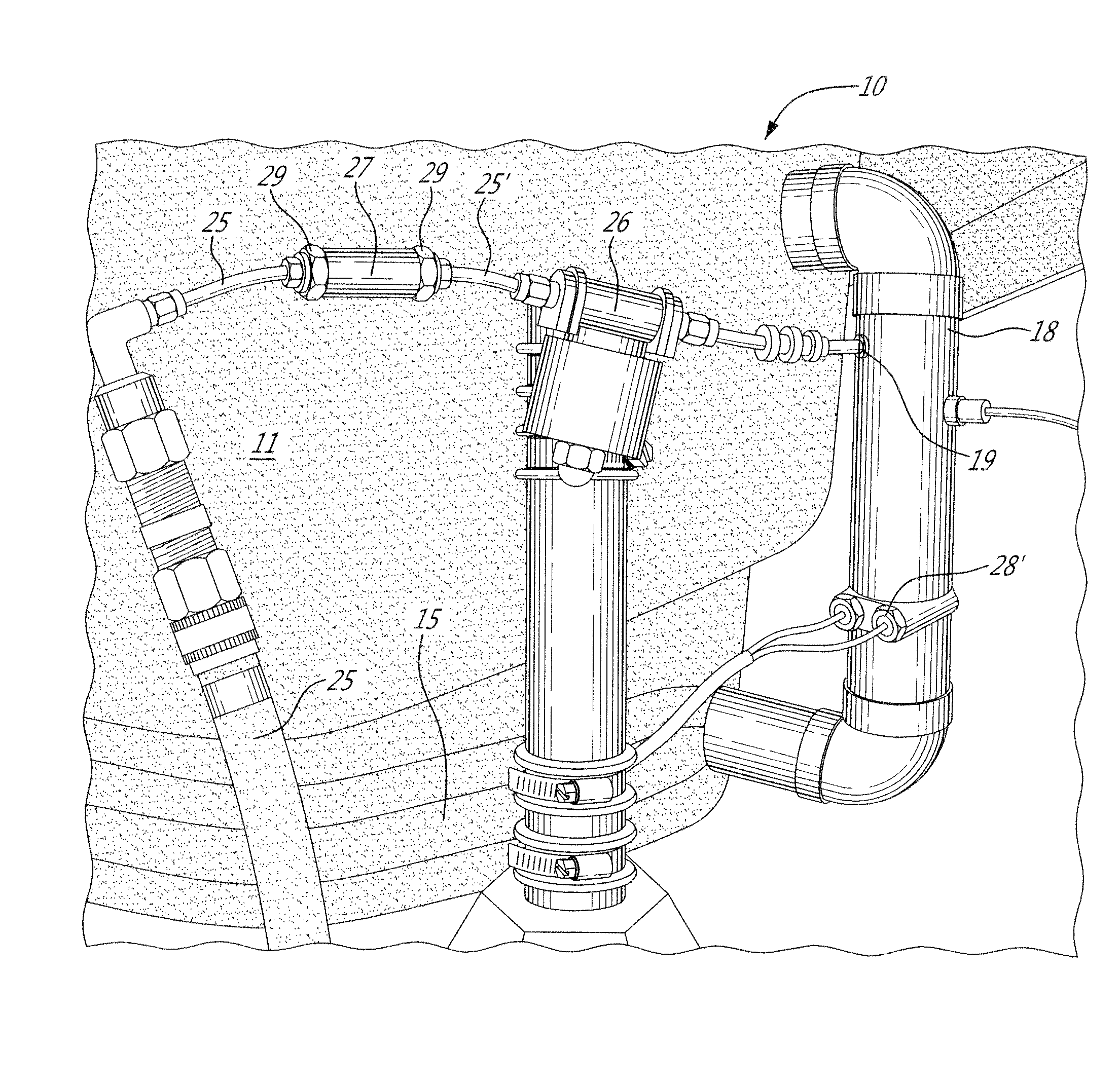
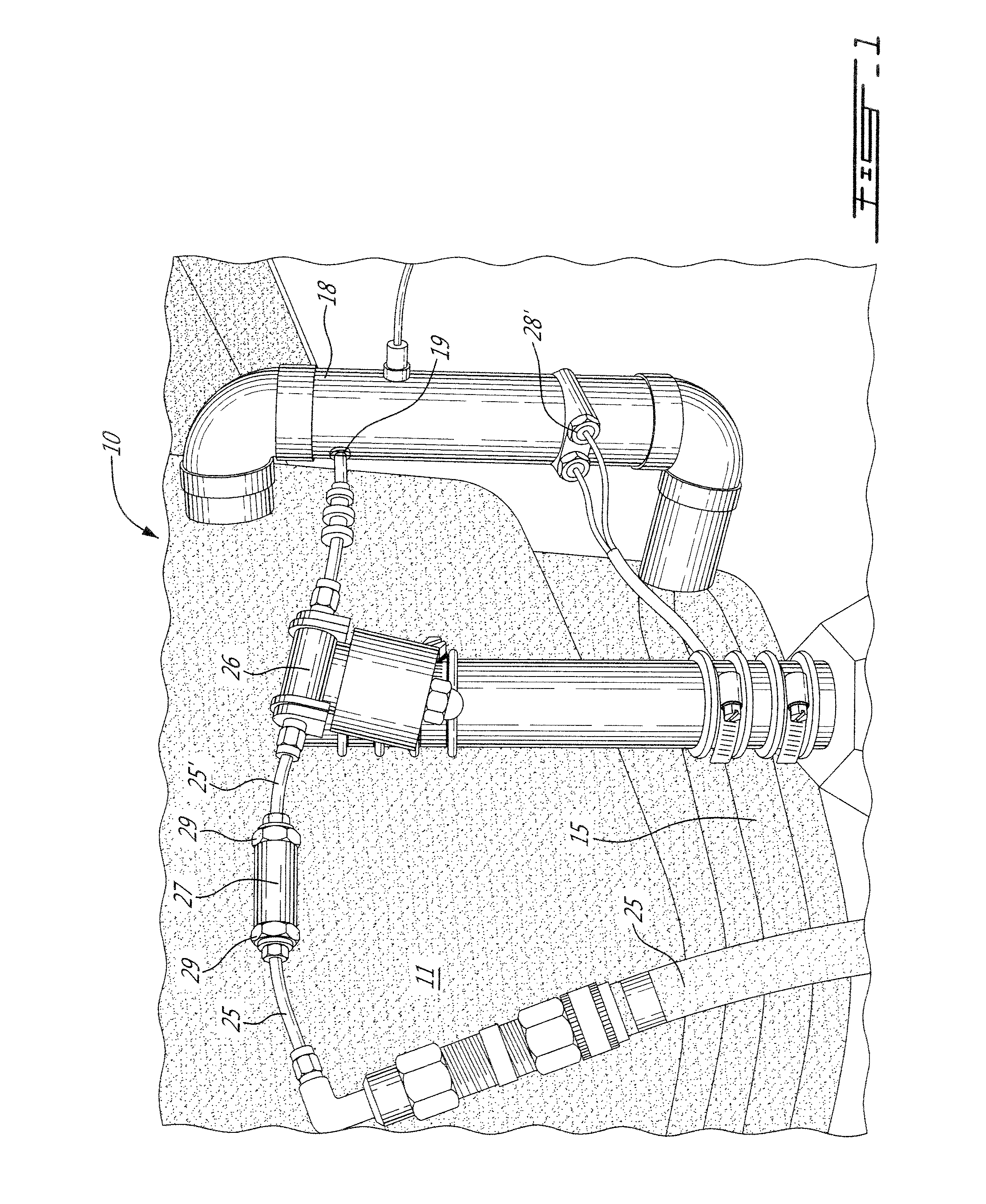
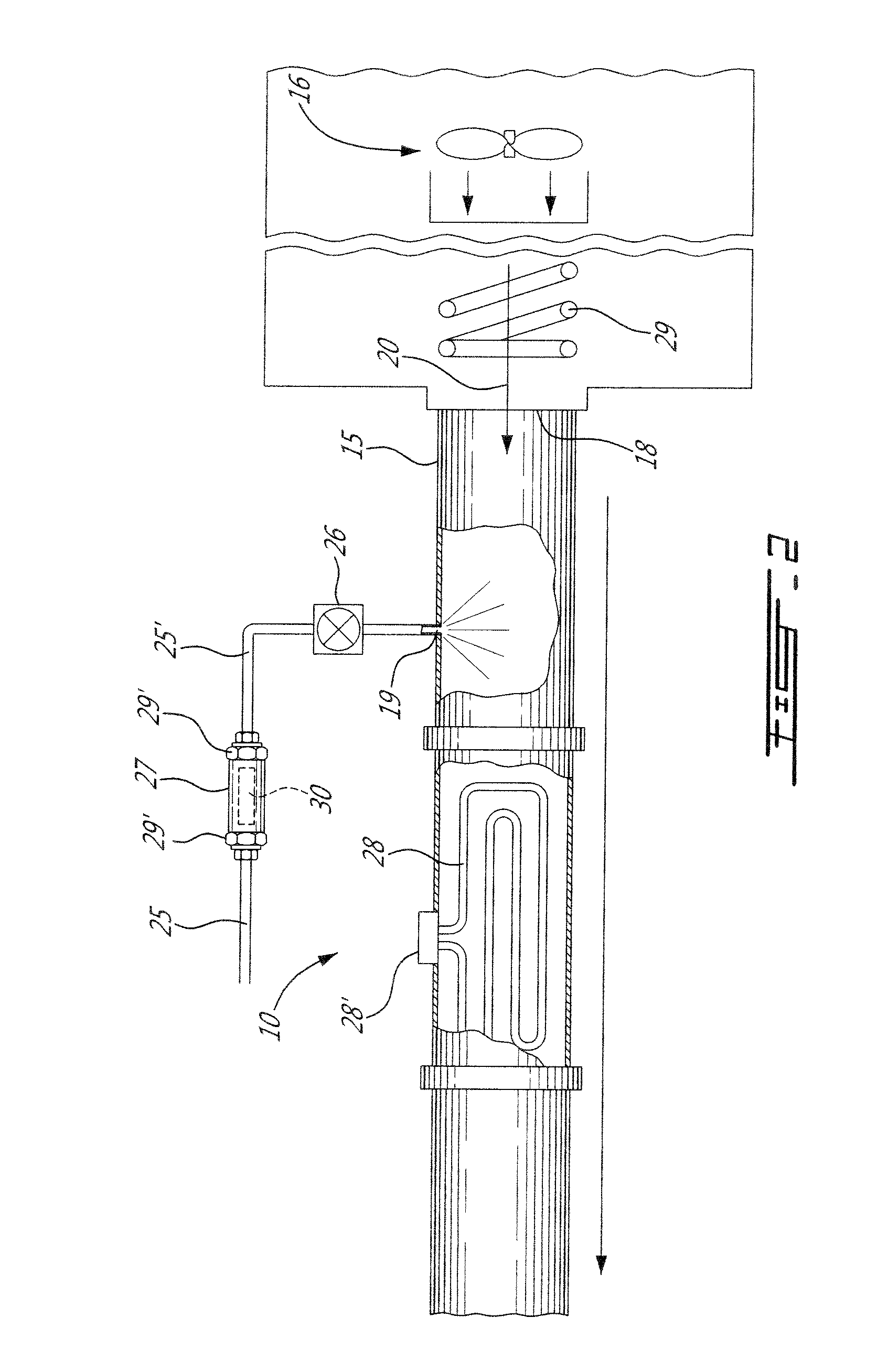
[0017]Referring to the drawings and more particularly to FIGS. 1 to 3, there is shown generally at 10 an air injection system for a hydro-massaging bath 11 constructed in accordance with the present invention. A hydro-massaging bath also includes indoor and outdoor spas having a hybrid system. The bath 11 has a bottom wall 12 and peripheral side walls 13. A plurality of air injecting orifices 14 are provided and distributed at least along some of the peripheral side walls 13. An air convecting conduit 15 surrounds the air injecting orifices 14. Accordingly, when air under pressure by a blower 16 is injected within the air convecting conduit 15 air will enter under pressure into the hot water 17 contained within the bathtub and create a turbulence in the water.

[0018]As more clearly shown in FIG. 2, the blower 16 injects air under pressure in an entry opening 18 of the air convecting conduit 15 and a water spray injector 19 spaced from the entry opening 18 injects a spray of water wit...


PUM


Abstract

An air injection system for a hydro-massaging bath is described. An air convecting conduit is in communication with a plurality of injecting orifices formed in a peripheral wall of the bath. An air blower injects air under pressure in an entry opening of the air convecting conduit. A water spray injector is located downstream of the entry opening and upstream of the air injecting orifices to inject a spray of a predetermined volume of water in the injected air under pressure. A water supply conduit is connected to the water spray injector and has a flow regulating valve to regulate the volume of water spray injected in the heated air to saturate the air with water. A shut-off valve is provided in the water supply conduit, and a heater is disposed in the air convecting conduit downstream of the water spray injector and upstream of the air injecting orifices wherein heated, humidified air injected in the water contained within the bathtub does not produce a cool sensation on the body of a user person.

Description

TECHNICAL FIELD[0001]The present invention relates to an air injection system for a hydro-massaging bath to eliminate the effect of coolness on the body of a user person immersed in hot water within the bath and in close proximity to air injecting orifices.BACKGROUND ART[0002]It is well known to inject air in the hot water contained in a bathtub to provide a turbulence of the water whereby a user person receives a massaging therapy by the turbulent water. A plurality of orifices are distributed in the side walls of the bathtub in areas where a water massage is required such as in the back wall and lower side wall areas of the bathtub. Various hydro massaging baths are known and such comprise adjustable nozzle assemblies mounted on the wall of a bathtub to discharge high velocity jets of water to impinge upon the body of a user person. However, when injecting air within the hot water, the user person is subjected to a sensation of coolness where the air jets impact its wet body. This...

Claims


Application Information

Patent Timeline
IPC IPC(8): A61H33/06
CPCA61H33/02A61H33/026A61H33/028A61H2201/50A61H2033/002A61H2033/0037A61H2201/0228A61H33/6063
Inventor BRUNELLE, HENRYGENDREAU, LOUISGRENIER, DANNYBAILLARGEON, GUY
Owner GESTION ULTRA INT
Learn More