Load port

a technology of loading port and sluice chamber, which is applied in the direction of transportation and packaging, mechanical equipment, machines/engines, etc., can solve the problems of insufficient supply of purge gas, inconformity of structure, and higher cost of purging the atmosphere, so as to increase the efficiency of removing moisture, reduce the speed of replacement gas, and improve the effect of efficiency

Inactive Publication Date: 2013-01-03
RIGHT MFG
View PDF16 Cites 24 Cited by
  • Summary
  • Abstract
  • Description
  • Claims
  • Application Information

AI Technical Summary

Benefits of technology

[0045]Each of the plurality of outlet nozzles is arranged in agreement with the gap between the adjacent wafers in the direction in which the wafers are layered. Furthermore, the plurality of outlet nozzles is formed in the entirety of the gas supply plate. Accordingly, it is possible to decrease a velocity of the replacement gas even if a considerable amount of the replacement gas is ejected between the wafers at a time, allowing the replacement gas to move in a laminar flow. As a result, it is possible to increase the efficiency of removing moisture and foreign materials (particles) in the vicinity of a surface of a wafer.
[0046]The present invention supplies the replacement gas from the region facing the aperture of the wafer storage container and employs the inner wall of the curved surface of the wafer storage container and the partition to allow the replacement gas to circulate in the substantially entirety of the wafer storage container. Accordingly, a centrifugal force occurs, which causes the foreign materials to move from an inner periphery to an outer periphery of a wafer. In addition, it is possible to cause the foreign materials to move from the wafer storage container into the intermediate room along with a gas, by utilizing the pressure difference between the wafer storage container and the intermediate room. In this manner, it is possible to remove the foreign materials from the wafer storage container.
[0047]It is possible for the present invention to cause a gas that moves along the partition, which is a part of the gas circulating inside the wafer storage container, to move from the wafer storage container into the intermediate room through the plurality of inlet nozzles. Accordingly, it is possible to increase the efficiency associated with the replacement of gasses.
[0048]Since the present invention includes the passage that applies the fluid resistance to the gas moving from the receiving room into the intermediate room, it is possible to increase the air tightness of the intermediate room and provide easier pressure control of the intermediate room.

Problems solved by technology

In some cases, this leads to a problem of insufficient supply of the purge gas to the spaces between the adjacent wafers.
In some cases, even such an arrangement has a difficulty in sufficiently purging the atmosphere, and could lead to higher costs for purging the atmosphere.
This results in the problem that such a structure does not conform to the so-called SEMI standard, which specifies that any protrusion should be formed with a length of 100 mm or less from the wall face of a wafer processing apparatus.

Method used


Image

  • Load port
  • Load port
  • Load port

Examples


first embodiment

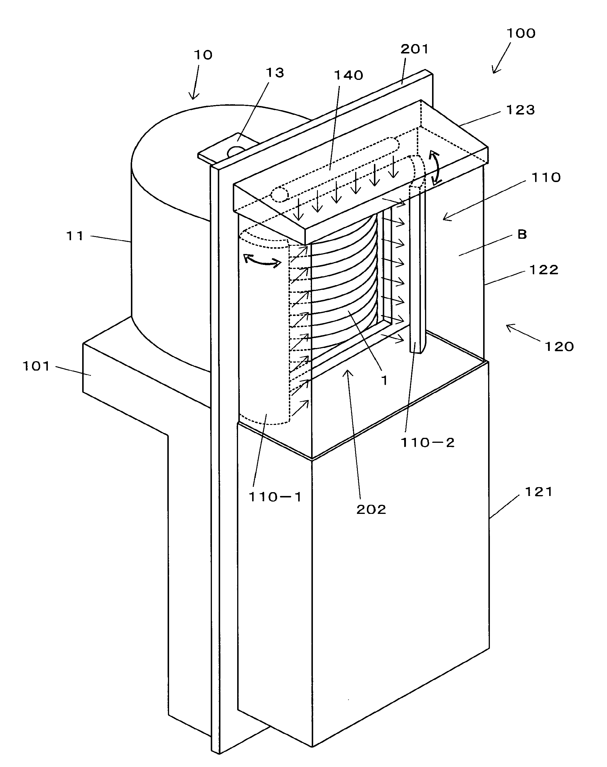
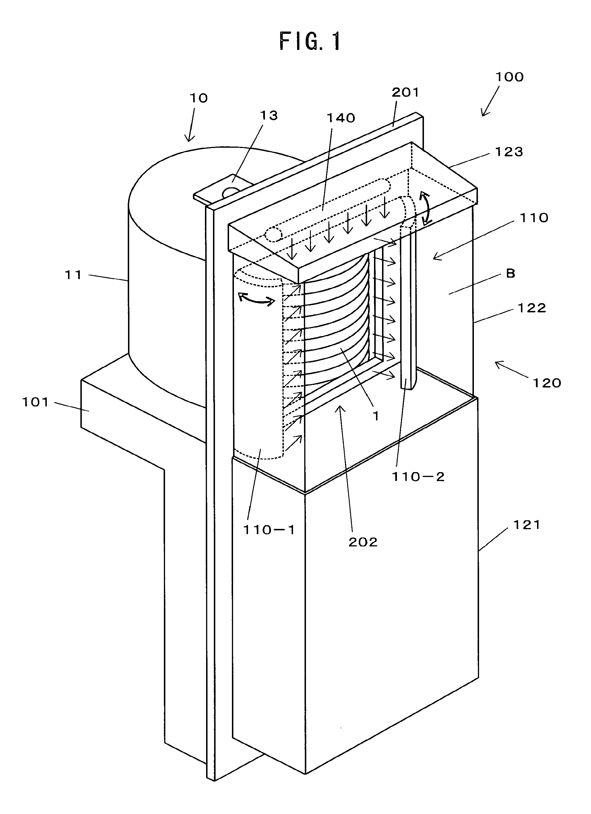
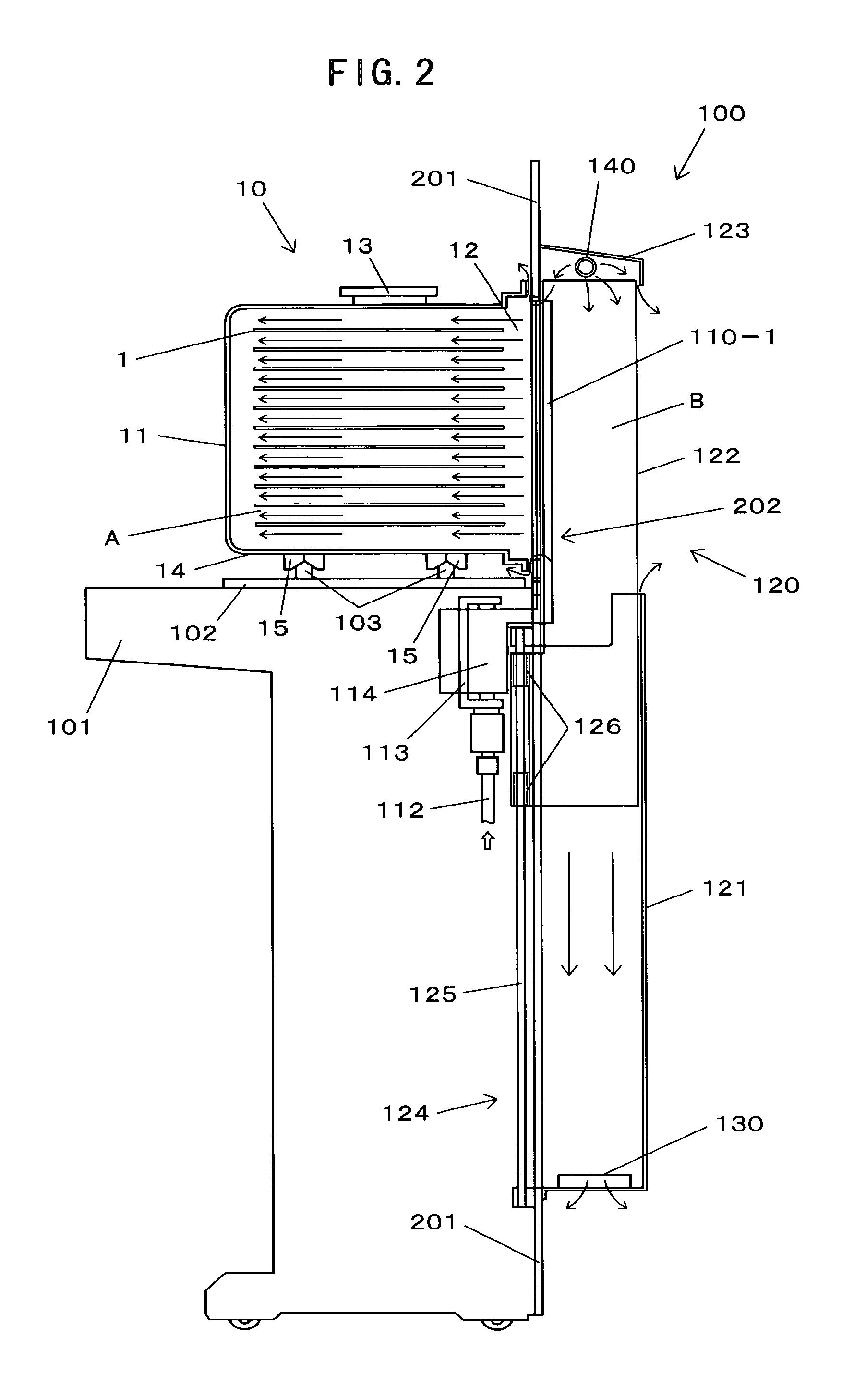
[0076]A load port 100 includes a wall face 201 or the like having a door opening portion 202 on which an unshown door member (which will be referred to as “load port door” hereafter) is detachably mounted. The load port 100 is installed on the wall face of an unshown wafer processing apparatus for performing predetermined processing for wafers 1.

[0077]As shown in FIG. 1, a wafer carrier 10 is a container for storing the wafers 1 therewithin at a predetermined pitch (at a pitch of around 10 mm). The wafer carrier 10 includes a carrier shell 11, and a carrier door 16 (see FIG. 3) or the like for sealing the container opening 12 of the carrier shell 11. Note that known examples of such carriers include an FOUP (Front Opening Unified Pod) and an FOSB (Front Opening Shipping Box).

[0078]The carrier shell 11 includes a curved inner wall 11a (see FIG. 4) formed at a position opposite to the container opening 12. Furthermore, the carrier shell 11 includes a robot flange 13 on the upper porti...

second embodiment

[0120]As shown in FIG. 9, the difference between the load port 100A and the load port 100 is that the load port 100A includes a nozzle unit 110A instead of the nozzle unit 110.

[0121]The nozzle unit 110A comprises thin plate-shaped members that can be stored in a storage portion 121A. The nozzle unit 110A includes nozzle outlets formed approximately over the entire area thereof such that they correspond to the spaces between the adjacent wafers 1. The nozzle outlets are formed in the nozzle unit 110A in the shape of a matrix at predetermined intervals. Each nozzle outlet is formed with a diameter equal to or smaller than ½ of the thickness of the nozzle unit 110A (e.g., with a diameter of ⅓ of the thickness of the nozzle unit 110A).

[0122]As described above, the nozzle unit 110A comprises thin plate-shaped members. Accordingly, such an arrangement allows the nozzle unit 110A to be raised from the storage portion 121A by an appropriate nozzle unit elevator mechanism employing belts, ba...

third embodiment

[0126]As shown in FIG. 10, the difference between the load port 100B and the load port 100 is that the load port 100B includes a nozzle unit 110B instead of the nozzle unit 110.

[0127]The nozzle unit 110B comprises tube-shaped members that can be stored in a storage portion 121B. The nozzle unit 110B includes nozzle outlets formed at positions that correspond to the spaces A between the wafers 1. Each nozzle outlet is formed with a diameter equal to or smaller than ½ of the thickness of the nozzle unit 110B (e.g., with a diameter of ⅓ of the thickness of the nozzle unit 110B) (see FIG. 6).

[0128]As described above, the nozzle unit 110B is stored in the storage portion 121B. Accordingly, an arrangement in which a pipe for supplying the purge gas is connected to the lower portion of the nozzle unit 110B suffices. That is to say, there is no need to provide a particular mechanism for turning the nozzle unit 110 as shown in FIG. 2, for example.

[0129]Such an arrangement provides a simple m...


PUM


Abstract

A load part has a nozzle unit having outlets for generating outflow and/or inflow of gas used for replacing the atmosphere of a wafer storage container, in a direction approximately parallel to spaces between adjacent wafers being stored, are a driving unit for extending the nozzle unit to a door opening portion.

Description

CROSS-REFERENCE TO RELATED APPLICATIONS[0001]The instant application is a continuation-in-part of U.S. patent application Ser. No. 11 / 630,123, filed Dec. 19, 2006, now pending, and incorporated by reference herein.BACKGROUND OF THE INVENTION[0002]1. Field of the Invention[0003]The present invention relates to a load port which is provided for a wafer processing apparatus for transferring various kinds of substrates (which will be referred to as “wafers” hereafter) such as silicon wafers, and which has a function of detaching / mounting a lid member (which will be referred to as “carrier door” hereafter) of a wafer storage container (which will be referred to as “wafer carrier” hereafter) for storing wafers at a predetermined pitch.[0004]2. Related Art[0005]Known examples of such kinds of conventional load ports include an arrangement that includes a load port door which has a function of engaging with a carrier door, and a load port door opening / closing mechanism that allows the load ...

Claims


Application Information

Patent Timeline
Patent Type & Authority Applications(United States)
IPC IPC(8): F03B11/02
CPCH01L21/67772Y10S414/135Y10T137/8593
Inventor YOSHIMURA, TAKEHIKONAGATA, TATSUHIKOSEKI, MASARUCHO, YOSHINORI
Owner RIGHT MFG
Why Eureka
Try Eureka