Display apparatus

a technology of display apparatus and display screen, which is applied in the direction of electrical apparatus, thermoelectric device junction materials, and semiconductor devices, etc., can solve the problems of unnatural luminance characteristics and increased luminance at the larger radiation angle, and achieve good luminance characteristics

Active Publication Date: 2013-01-03
CANON KK
View PDF8 Cites 14 Cited by
  • Summary
  • Abstract
  • Description
  • Claims
  • Application Information

AI Technical Summary

Benefits of technology

[0010]With the embodiment of the present invention, a good luminance characteristic is obtained in the di

Problems solved by technology

However, the display apparatus including the organic EL elements, in each of which a film thickness etc. are set to be adapted for utilizing the optical interference effect, and the lenses has a problem as f

Method used


Image

  • Display apparatus
  • Display apparatus
  • Display apparatus

Examples


example

[0078]A method of manufacturing the display apparatus according to the embodiment of the present invention is described in this EXAMPLE with reference to FIGS. 8A to 8D.

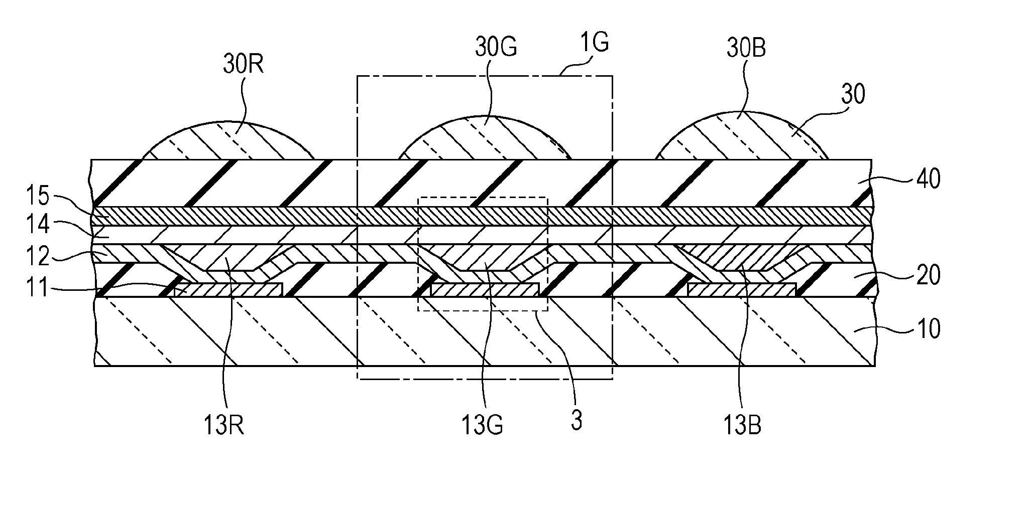
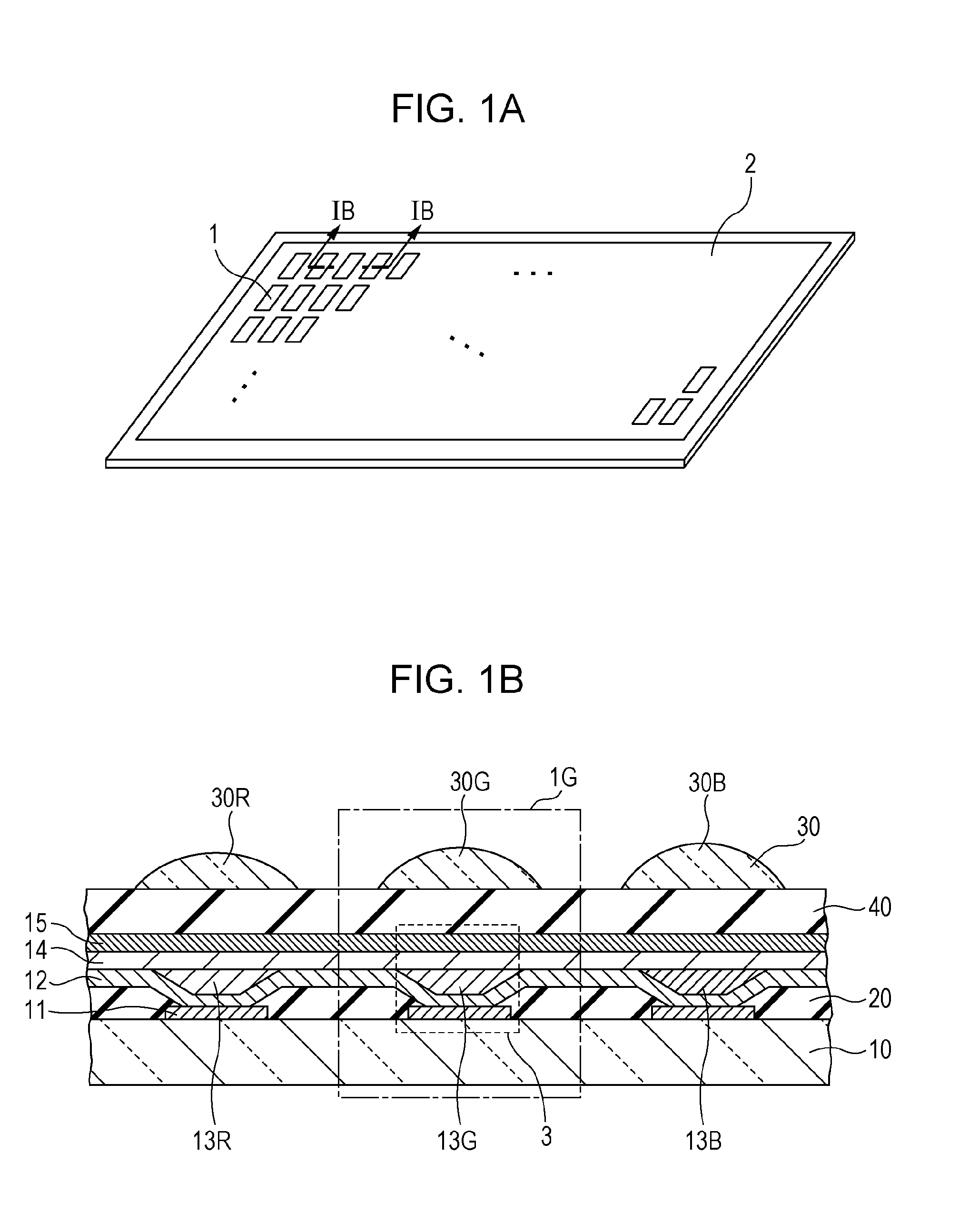
[0079]A substrate 10, illustrated in FIG. 8A, was prepared by forming, on a glass substrate, a pixel circuit (not illustrated) by using a low-temperature polysilicon TFT liquid crystal, and forming an interlayer insulating film made of SiN and a planarizing film made of an acryl resin on the pixel circuit in that order. On the substrate 10 thus obtained, an ITO film and an AlNd film were formed by sputtering in thicknesses of 40 nm and 100 nm, respectively. The ITO film and the AlNd film were then subjected to patterning per pixel, whereby the first electrodes 11 were formed. The reflective surface provided by the first electrode 11 was an interface between the ITO film and the AlNd film. Phase shifts caused upon light being reflected at the interface were 2.42 [rad], 2.15 [rad], and 1.81 [rad] at wavelengths of 620 ...


PUM


Abstract

In a display apparatus including an organic EL element utilizing the optical interference effect, and a lens, a diameter of the lens is set such that, of light radiated from the organic EL element into a protective layer, light radiated at a larger angle than an angle, at which a light intensity distribution of the light radiated into the protective layer with respect to a radiation angle of the light takes a local minimum value, is not output to the outside of the display apparatus.

Description

BACKGROUND OF THE INVENTION[0001]1. Field of the Invention[0002]The present invention relates to a display apparatus including an organic electroluminescence (EL) element.[0003]2. Description of the Related Art[0004]Recently, a display apparatus including organic EL elements, each having an organic compound layer between a pair of electrodes, has been developed with more eagerness. Regarding that type of organic EL element, as discussed in International Publication WO2001 / 039554, it is known that color purity and luminous efficiency of a luminescent color are improved by utilizing the optical interference effect. In more detail, an optical distance (optical path length) H between two electrodes is expressed by the following formula 1 by using an angle Θ of light emitted from the organic EL element (Θ is 0 degree when the light is visually recognized in a direction rightly facing the element), the sum φ of phase shifts caused when the emitted light is reflected at the two electrodes,...

Claims


Application Information

Patent Timeline
IPC IPC(8): H01L27/32
CPCH01L51/5265H01L27/3211H01L51/5275H10K59/35H10K50/852H10K50/858
Inventor ICHINOSE, YUUSHISUMIDA, NOA
Owner CANON KK
Why Eureka
Try Eureka