Radome Attachment Band Clamp
a technology of radome and band clamp, which is applied in the direction of antenna details, antennas, coatings, etc., can solve the problems of increased manufacturing complexity and/or cost, unusable backlobes, and increased metalizing operations,
- Summary
- Abstract
- Description
- Claims
- Application Information
AI Technical Summary
Benefits of technology
Problems solved by technology
Method used
Image
Examples
second embodiment
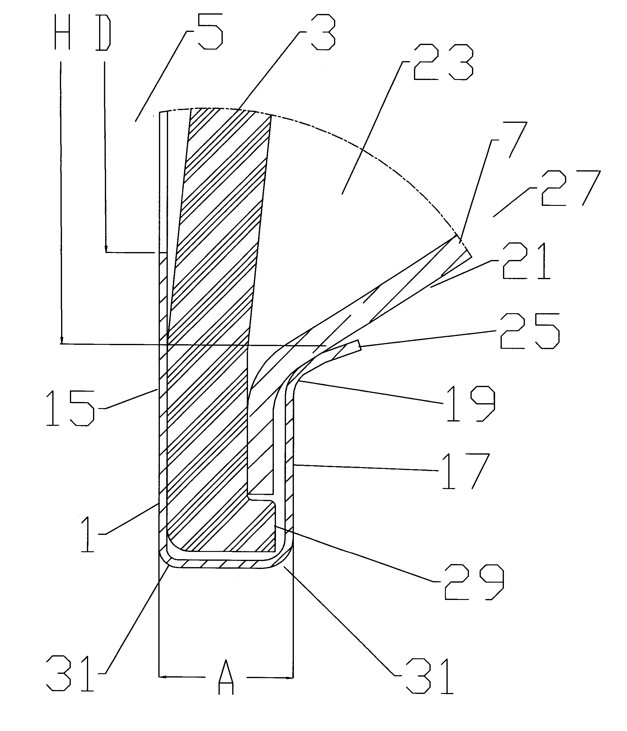
[0066]One skilled in the art will appreciate that the optimal range of widths “A” may be difficult to achieve for some operating frequencies without incorporating further structure in the radome and / or reflector dish periphery. In a second embodiment, for example as shown in FIG. 11, the width “A” may be increased via the application of a fold 33 in the band clamp from the desired extent of the width “A” back toward the reflector dish 7. The pictured embodiment is simplified for demonstration purposes with respect to extending the width “A” but may similarly be applied with a fold 33 and proximal lip 17 that extends further inward and includes a turnback region 19 contacting the outer surface 21 of the signal area 23 of the reflector dish 7.
third embodiment
[0067]In a third embodiment, for example as shown in FIG. 12, an extension of the width “A” may be cost effectively achieved by attaching a further width ring 35 of metallic and / or metal coated material to the band clamp 1 outer diameter. The width ring 35 may be applied with any desired width, cost effectively securely attached by spot welding or fasteners such as screws, rivets or the like.
[0068]FIG. 13 illustrates 18 GHz band RF modeling software predictions of F / B improvement between a width ring 35 width “A” of 0.5 and 1.2 wavelengths. Measured co-polar and cross-polar F / B performance of a FIG. 12 band clamp 1 with width ring 35 of width “A”=0.5 wavelengths is shown in FIGS. 14 and 15. Note the performance meets the regulatory envelope across the entire range, but with no margin. However, as shown in FIGS. 16 and 17, the measured co-polar and cross-polar F / B performance of a FIG. 12 band clamp 1 with width ring 35 of width “A”=1.2 wavelengths is significantly improved and well ...
fourth embodiment
[0069]In a fourth embodiment, the width ring 35 may be provided in an angled configuration as demonstrated in FIG. 18. As shown in FIG. 19, RF modeling software predictions of F / B improvement indicate progressively increasing improvement as the angle applied increases from zero (flat width ring cross section) to sixty degrees of diffraction gradient.
[0070]In further embodiments, structures similar in electrical effect to the width ring 35 may be formed integral with the band clamp cross section as a protruding portion 37 of desired dimension. These complex structures may be cost efficiently formed with high precision via, for example, extrusion, injection molding, progressive punching and / or stretch forming. As shown for example in FIGS. 20-39, the protruding portion 37 creates a band clamp 1 with a generally uniform cross section in which the proximal lip 17, distal lip 15 and protruding portion 37 form a unitary contiguous portion. One skilled in the art will appreciate that the u...
PUM
 Abstract
Description
Claims
Application Information
 - R&D
- Intellectual Property
- Life Sciences
- Materials
- Tech Scout
- Unparalleled Data Quality
- Higher Quality Content
- 60% Fewer Hallucinations
Browse by: Latest US Patents, China's latest patents, Technical Efficacy Thesaurus, Application Domain, Technology Topic, Popular Technical Reports.
© 2025 PatSnap. All rights reserved.Legal|Privacy policy|Modern Slavery Act Transparency Statement|Sitemap|About US| Contact US: help@patsnap.com


