Base station device and terminal device

Inactive Publication Date: 2013-01-03
SUMITOMO ELECTRIC IND LTD
View PDF18 Cites 40 Cited by
  • Summary
  • Abstract
  • Description
  • Claims
  • Application Information

AI Technical Summary

Benefits of technology

[0025]The present invention is made in view of the above-described problems, and has an object (first object) to enable the scheduler to quickly deal with information while suppressing increase in the load on the MAC.
[0096]Since an area where such reception time difference occurs is limited, the position estimation unit can estimate that the position of the base station device exists in the area where the reception time difference occurs. For example, an area in which broadcast waves of the same frequency, which have been simultaneously transmitted from two broadcast stations, are received with a predetermined reception time difference is an area on a hyperbolic curve between the two broadcast stations. In this way, the area in which the reception time difference occurs can be limited, and the area can be used for estimation of the position of the base station device.

Problems solved by technology

In a wireless communication system having a plurality of base station devices, if communication areas (cells) set by the respective base station devices overlap each other, a signal transmitted from a certain base station device may reach a terminal device existing in a cell of another base station device located near the base station device, and the signal may become an interference signal for the terminal device.

Method used


Image

  • Base station device and terminal device
  • Base station device and terminal device
  • Base station device and terminal device

Examples


Embodiment Construction

[0130]

[0131]Hereinafter, an embodiment of the present invention will be described in detail with reference to the drawings.

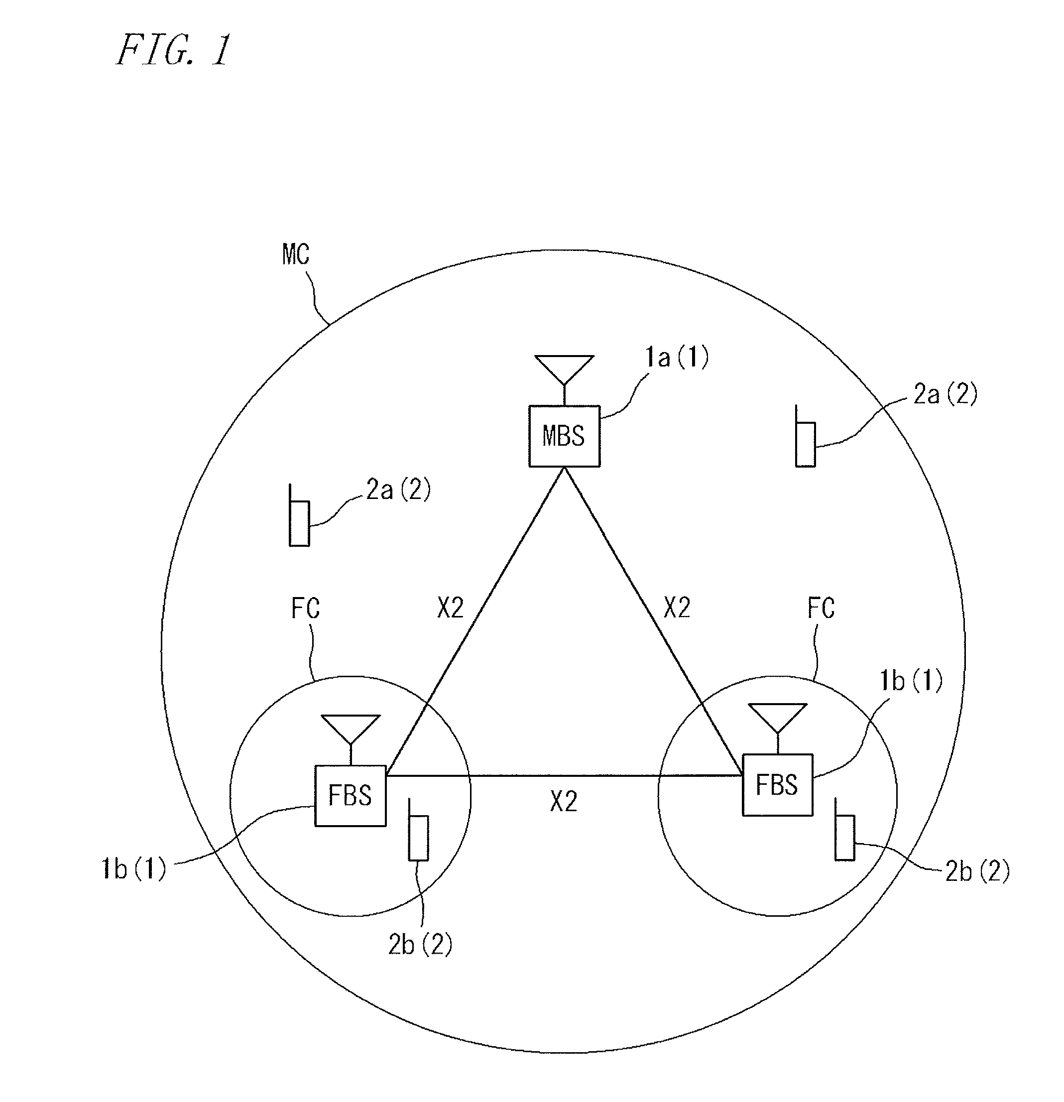
[0132]FIG. 1 illustrates a configuration of a wireless communication system including a base station device of the present invention. The wireless communication system of the present embodiment is, for example, a system for mobile phones to which LTE (Long Term Evolution) is applied, and communication based on the LTE is performed between each base station device and each terminal device. However, the communication scheme is not limited to the LTE.

[0133]The wireless communication system includes a plurality of base station devices 1. A terminal device (mobile station) 2 as a mobile terminal is allowed to wirelessly access any of the base station devices 1, and communicate with the base station device 1.

[0134]The base station devices 1 provided in the wireless communication system include: a macro base station device 1a forming a communication area (macro cell) M...


PUM


Abstract

A base station device is provided with a MAC unit 30 which performs processing on a MAC layer for wireless communication, a scheduler 10 which performs scheduling for determining allocation of radio resources, and a radio resource management unit 70 which manages the radio resources. The scheduler 10 is connected to the radio resource management unit 70 so as to obtain information from the radio resource management unit 70 without intervention of the MAC unit 30.

Description

TECHNICAL FIELD[0001]The present invention relates to base station devices and terminal devices.BACKGROUND ARTBackground Art 1[0002]A base station device is provided with a scheduler that performs scheduling to determine radio resources (frequencies, times, and the like) to be allocated to terminal devices.[0003]The scheduler enables to appropriately determine allocation of radio resources to each terminal in accordance with the radio wave condition or the like.[0004]In LTE (Long Term Evolution), the scheduler is configured as a function of MAC (Media Access Control; second layer) for wireless communication, i.e., as a MAC scheduler.[0005]FIG. 9 illustrates a layer structure relating to wireless communication of a base station device in the LTE. This layer structure includes PHY (Physical Layer) as a first layer relating to wireless communication, and MAC as a layer higher than the PHY. The scheduler is a function of the MAC.[0006]RLC (Radio Link Control) / PDCP (Packet Data Convergen...

Claims


Application Information

Patent Timeline
Patent Type & Authority Applications(United States)
IPC IPC(8): H04W72/04H04W72/10H04B15/00
CPCG01S5/0205H04W52/244H04W72/1231H04W80/02H04W88/08H04W52/346G01S5/0252G01S5/0278H04W28/048H04W72/082H04W72/0426G01S5/0009H04W28/04H04W72/27H04W72/542H04W72/541
Inventor YAMAMOTO, TAKASHITANAKA, YOSHIZOMOCHIDA, EIJI
Owner SUMITOMO ELECTRIC IND LTD
Why Eureka
Try Eureka