
Double Valve Block and Actuator Assembly Including Same

a technology of actuator assembly and valve block, which is applied in the direction of water supply installation, sealing/packing, and well accessories, etc., can solve the problems of consuming more pressurized hydraulic fluid, and unable to meet the requirements of rain actuation,

Inactive Publication Date: 2013-01-10
CAMERSON INT CORP
View PDF6 Cites 9 Cited by
  • Summary
  • Abstract
  • Description
  • Claims
  • Application Information

AI Technical Summary

Benefits of technology

The patent describes a valve and system for controlling the flow of fluid in a subsea wellbore. The valve has a housing with two chambers and a neutral chamber, and includes a first valve member and a second valve member. The system also includes a biasing member and an actuator assembly with a cylinder and piston. The actuator assembly is designed to transition between an open position and a closed position. The valve is used to control the flow of fluid between the two chambers and can open or close to allow or prevent fluid communication. The system can be used to drill a subsea wellbore and has various advantages over previous devices.

Problems solved by technology

For relatively deepwater subsea BOP stacks, supplying a sufficient volume and pressure of hydraulic fluid from the surface to actuate a rain may be challenging.
However, with a simple piston-cylinder assembly, the same volume of pressurized hydraulic fluid is required to open as well as close the ram.
Thus, opening the rain consumes more pressurized hydraulic fluid volume than is necessary and wastes the finite volume of pressurized hydraulic fluid in the subsea accumulators.

Method used


Image

  • Double Valve Block and Actuator Assembly Including Same
  • Double Valve Block and Actuator Assembly Including Same
  • Double Valve Block and Actuator Assembly Including Same

Examples


Embodiment Construction

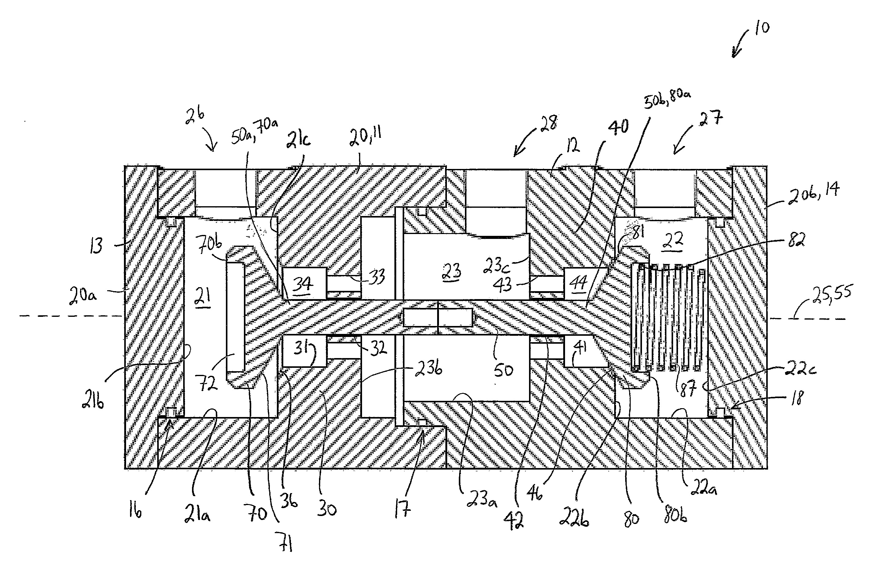
[0027]The following discussion is directed to various exemplary embodiments. However, one skilled in the art will understand that the examples disclosed herein have a broad application, and that the discussion of any embodiment is meant only to be exemplary of that embodiment, and not intended to suggest that the scope of the disclosure, including the claims, is limited to that embodiment.

[0028]Certain terms are used throughout the following description and claims to refer to particular features or components. As one skilled in the art appreciates, different persons may refer to the same feature or component by different names. This document does not intend to distinguish between components or features that differ in name but not function. The drawing figures are not necessarily to scale. Certain features and components may be shown exaggerated in scale or in somewhat schematic form and some details of conventional elements may not be shown in interest of clarity and conciseness.

[00...


PUM


Abstract

A valve comprises a housing including a first chamber, a second chamber, and a neutral chamber. In addition, the valve comprises a stem disposed within the housing. Further, the valve comprises a first valve member at least partially disposed in the first chamber and connected to the stem and a second valve member at least partially disposed in the second chamber and connected to the stem. The first valve member has a closed position seated in a first annular valve seat and an open position spaced apart from the first valve seat. The second valve member has a closed position seated in a second annular valve seat and an open position spaced apart from the second valve seat. Moreover, the valve comprises a biasing member configured to bias the second valve member to the closed position and the first valve member to the open position.

Description

CROSS-REFERENCE TO RELATED APPLICATIONS[0001]Not applicable.STATEMENT REGARDING FEDERALLY SPONSORED RESEARCH OR DEVELOPMENT[0002]Not applicable.BACKGROUND[0003]1. Field of the Invention[0004]The present invention relates generally to a double valve. More particularly, the present invention relates to a double valve that allows an unpressurized port and a balance port to be in fluid communication when a pressurized port is closed.[0005]2. Background of the Technology[0006]In most offshore-drilling operations, a wellhead at the sea floor is positioned at the upper end of the subterranean wellbore lined with casing, a blowout-preventer (BOP) stack is mounted to the wellhead, and a lower-marine-riser package (LMRP) is mounted to the BOP stack. The upper end of the LMRP typically includes a flex joint coupled to the lower end of a drilling riser that extends upward to a drilling vessel at the sea surface. A drill string is hung from the drilling vessel through the drilling riser, the LMR...

Claims


Application Information

Patent Timeline
Patent Type & Authority Applications(United States)
IPC IPC(8): E21B7/12F15D1/00F16K31/00
CPCE21B33/062F15B13/0405E21B34/10E21B34/04E21B33/06F16K11/048Y10T137/2544Y10T137/0318Y10T137/88046E21B33/0355E21B33/063E21B33/064
Inventor ARTEAGA, NICOLAS
Owner CAMERSON INT CORP
Learn More