Motion-based power assist system for wheelchairs

a technology of power assist system and manual wheelchair, which is applied in the direction of dynamo-electric converter control, instruments, tractors, etc., can solve the problems of difficult to get the wheelchair into and out of the car for even the strongest user, add and also affect the battery life. , to achieve the effect of easy transportation and significant weight to the wheelchair

Active Publication Date: 2013-01-10
MAX MOBILITY
View PDF30 Cites 54 Cited by
  • Summary
  • Abstract
  • Description
  • Claims
  • Application Information

AI Technical Summary

Benefits of technology

[0010]By using the kinematics of the power assist system, the system will be able to recognize different situations and adjust its contribution to the user's propulsion to compensate. By measuring the kinematics of the power assist system, the present invention can recognize situations when the user is trying to stop, slow down, or is beginning to tip, and in response cut off all driving assistance. The use of the power assist system motion and kinematics as the input to the push activation control is novel. Prior art devices tend to add significant weight to the wheelchair, making it difficult to get the wheelchair into and out of a car for even the strongest user. Battery life is also an issue because the power assist wheels are simply too heavy to push around without the power assist.
[0011]In one exemplary embodiment of the invention, the aforementioned motion-based push activation is employed on a single drive wheel attachment that mounts to the axle of a wheelchair midway between the rear wheels. Attachment mounts are clamped to the axle and attach to the drive wheel attachment, allowing for quick connecting and releasing of the system for easy transport.

Problems solved by technology

Prior art devices tend to add significant weight to the wheelchair, making it difficult to get the wheelchair into and out of a car for even the strongest user.
Battery life is also an issue because the power assist wheels are simply too heavy to push around without the power assist.

Method used


Image

  • Motion-based power assist system for wheelchairs
  • Motion-based power assist system for wheelchairs
  • Motion-based power assist system for wheelchairs

Examples


Embodiment Construction

[0019]In various exemplary embodiments, the present invention comprises a power assist system used on a manual wheelchair. Motion-based instrumentation measures the kinematics of the power assist system. The kinematics measured include, but are not limited to, linear velocities, angular velocities, linear accelerations, and angular accelerations. These parameters are quantified using a range of instruments, including but not limited to, gyroscopes, encoders, potentiometers, inertia measuring units, and multi-axis accelerometers. From these motion-based measurements, push activation can be recognized.

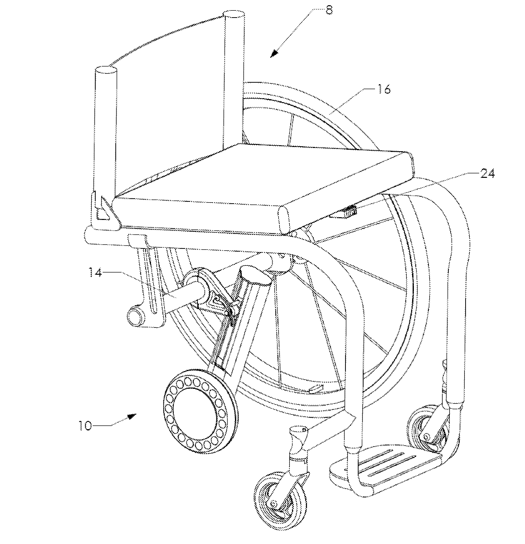
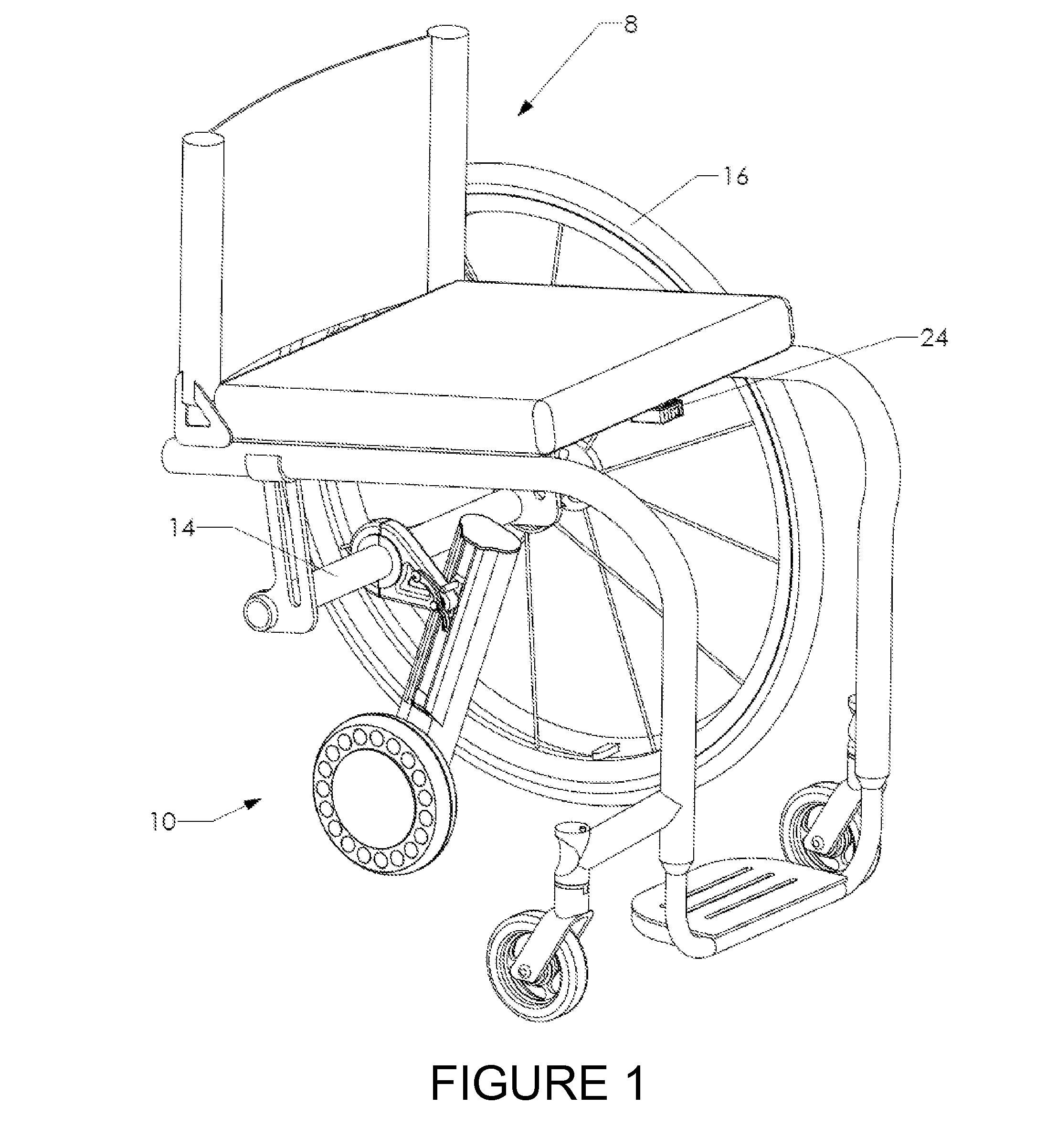
[0020]The push activation recognition employs the principle that when the user is applying a push to the rim mounted handrim of typical wheelchair rear wheels 16 on a generic manual wheelchair 8, as shown in FIG. 1, the wheelchair rear wheels 16 are being accelerated by the user. If the rear wheels 16 are experiencing an angular acceleration then the wheelchair 8 and all onboard parts wi...


PUM


Abstract

A motion-based push activation power assist system for manual wheelchairs. The system uses motion-based measurements to determine when the user applies a push to the wheelchair handrims and brakes with the handrims. The push recognition activates a drive system that provides an assistive driving force-pulse to the wheelchair to reduce the demand on the user during propulsion. The brake recognition deactivates the power assist. The provided power assist is proportional to the sensed push and can be modulated to different proportional settings.

Description

[0001]This application claims benefit of and priority to U.S. Provisional Application No. 61 / 504,949, filed Jul. 6, 2011, by Mark Richter, and is entitled to that filing date for priority. The specification, figures and complete disclosure of U.S. Provisional Application No. 61 / 504,949 are incorporated herein by specific reference for all purposes.FIELD OF INVENTION[0002]This invention relates to a power assist system for manual wheelchairs, specifically a system that employs motion-based sensing for recognition of user propulsion and braking.BACKGROUND OF THE INVENTION[0003]Manual wheelchairs are the primary mode of locomotion for millions of people around the world. Upper limb pain and injury is very common among these manual wheelchair users and can severely impact mobility, independence and quality of life. The most common types of injury are impingement syndrome of the shoulder and carpal tunnel syndrome of the wrist. Upper limb pain and injury is an emotionally, physically and...

Claims


Application Information

Patent Timeline
Patent Type & Authority Applications(United States)
IPC IPC(8): A61G5/04G08C17/00H02P31/00B62M6/40
CPCA61G5/04A61G2005/048A61G2203/36A61G5/047A61G2203/30A61G5/048A61G5/045A61G2203/12
Inventor RICHTER, W. MARK
Owner MAX MOBILITY
Why Eureka
Try Eureka