

Detector
a detector and detector technology, applied in the field of composite type detectors, can solve problems such as difficulty in quickly and appropriately responding to various types of fires
- Summary
- Abstract
- Description
- Claims
- Application Information
AI Technical Summary
Benefits of technology
Problems solved by technology
Method used
Image

Examples
first embodiment
[0042]First, a first embodiment is described. This embodiment relates to a detector including a smoke sensor and a gas sensor.
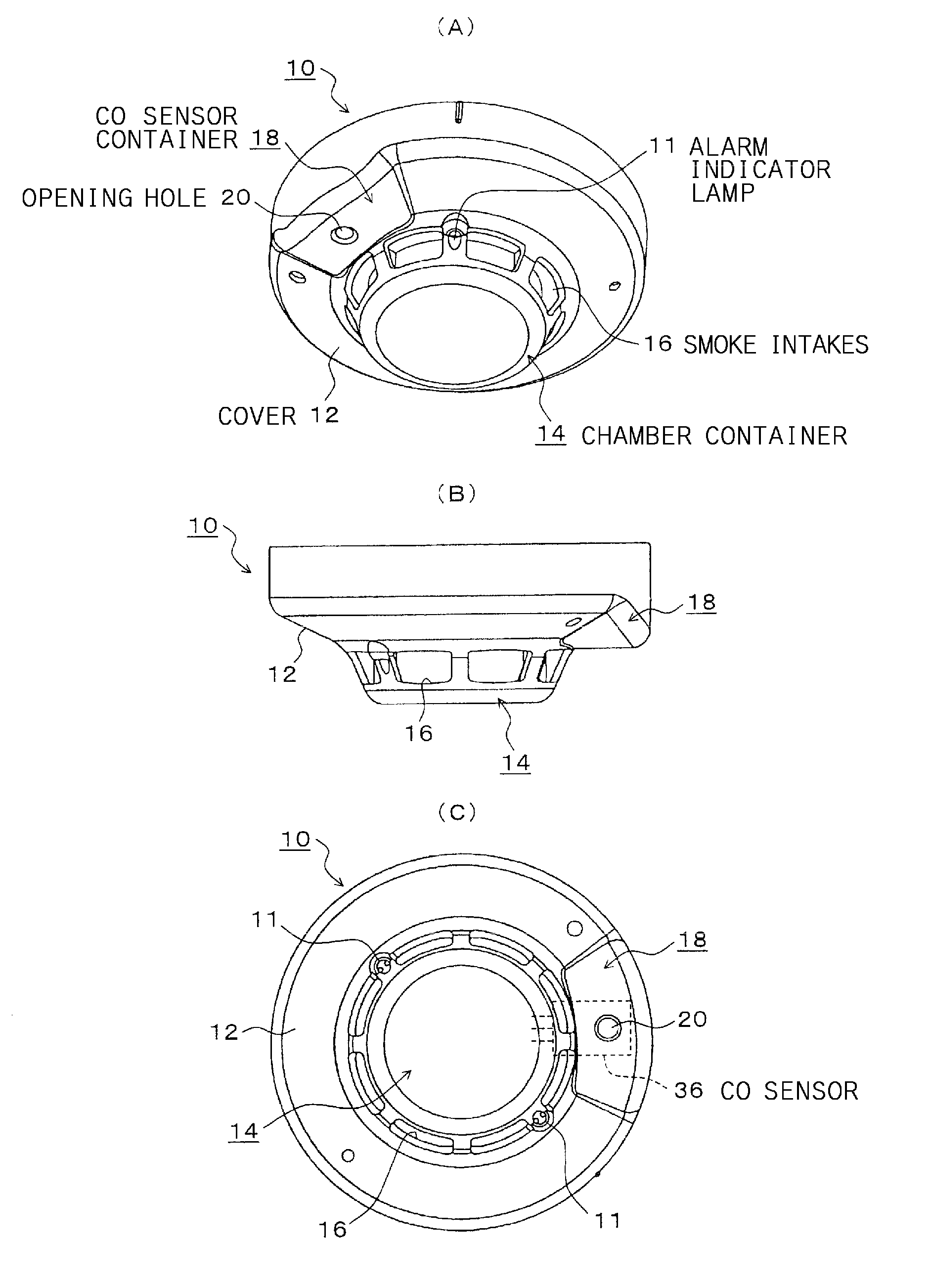
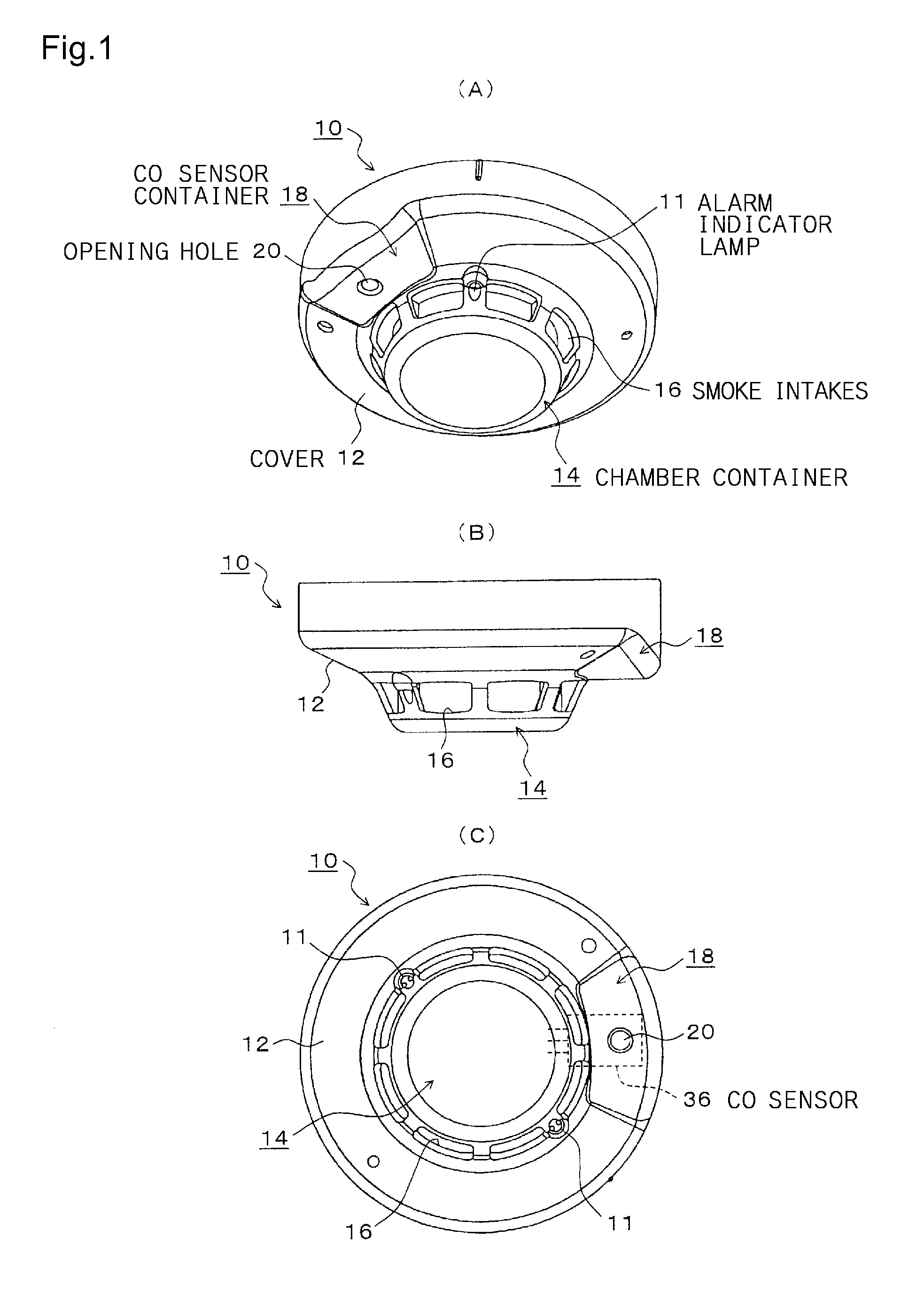
[0043]FIG. 1 is an illustration showing an embodiment of a composite-type detector in accordance with the invention, including a smoke sensor as a fire sensor and a CO sensor as a gas sensor for detecting gas generated by a fire. FIG. 1(A) is a view seen from below of the detector mounted on a ceiling surface. FIG. 1(B) is a side view of the detector. FIG. 1(C) is a plan view seen from below of the detector.
[0044]In FIG. 1, a detector 10 of the embodiment includes: a detector main body contained in the detector 10; and a cover (detector cover) 12 placed outside the main body. The cover 12 includes a chamber container (container) 14 formed downwardly from the center of an approximately cylindrical base portion. A plurality of smoke intakes (intakes) 16 are open around the chamber container 14. An alarm activation indicator lamp 11 is provided on the side surfa...
second embodiment
[0122]Next, a second embodiment is described. This embodiment relates to a detector including a smoke sensor, a gas sensor and, additionally, a temperature sensor. Note that, among components of the second embodiment, components not specifically described are intended to be similar to those of the first embodiment. The components similar to those of the first embodiment are appropriately denoted by the same numerals as those of the first embodiment, and will not be repeatedly described.
[0123]FIG. 14 is an illustration showing another embodiment of the detector in accordance with the invention, which detects heat (temperature), smoke and CO. FIG. 14(A) is a perspective view seen from below of the detector mounted on a ceiling surface. FIG. 14(B) is a side view of the detector. FIG. 14(C) is a plan view seen from below of the detector.
[0124]As shown in FIG. 14, the detector 10 of the embodiment includes: the smoke intakes 16 formed around the chamber container 14 protruding from the c...
third embodiment
[0157]Next, a third embodiment is described. This embodiment relates to a detector including a smoke sensor, a gas sensor and, additionally, a temperature sensor as with the second embodiment, but having a different structure from the detector of the second embodiment. Note that, among components of the third embodiment, components not specifically described are intended to be similar to those of the second embodiment. The components similar to those of the second embodiment are appropriately denoted by the same numerals as those of the second embodiment, and will not be repeatedly described.
[0158]FIG. 19 is an illustration showing another embodiment of the detector in accordance with the invention, which detects heat, smoke and CO. FIG. 19(A) is a perspective view seen from below of the detector mounted on a ceiling surface. FIG. 19(B) is a side view of the detector. FIG. 19(C) is a plan view seen from below of the detector. Furthermore, FIG. 20 is a cross-sectional view taken in t...
PUM
 Abstract
Description
Claims
Application Information