
Surface mounted LED package and manufacturing method therefor

a technology of led packaging and manufacturing method, which is applied in the direction of solid-state devices, basic electric elements, electric devices, etc., can solve problems such as reliability problems, and achieve the effects of reducing the height shortening the length of the bonding wire, and reducing the problem of potential reliability problems

Inactive Publication Date: 2013-01-10
LITE ON SINGAPORE PTE LTD
View PDF5 Cites 9 Cited by
  • Summary
  • Abstract
  • Description
  • Claims
  • Application Information

AI Technical Summary

Benefits of technology

The patent text describes a new surface mounted LED package that has several advantages. First, it reduces the length of the bonding wire, which helps to improve reliability and lower the risk of circuit shorts. Second, the package as a whole is smaller, as it uses a more efficient design. Additionally, the conductive layer in the package can also act as a reflecting surface, which can improve its overall performance.

Problems solved by technology

In the meantime, it causes the potential reliability issues.

Method used


Image

  • Surface mounted LED package and manufacturing method therefor
  • Surface mounted LED package and manufacturing method therefor
  • Surface mounted LED package and manufacturing method therefor

Examples


Embodiment Construction

[0022]In order to better understand the objective, structure, characteristics, and effects of the instant disclosure, a description relating thereto will be made with reference to preferred embodiments thereof and the accompanying drawings.

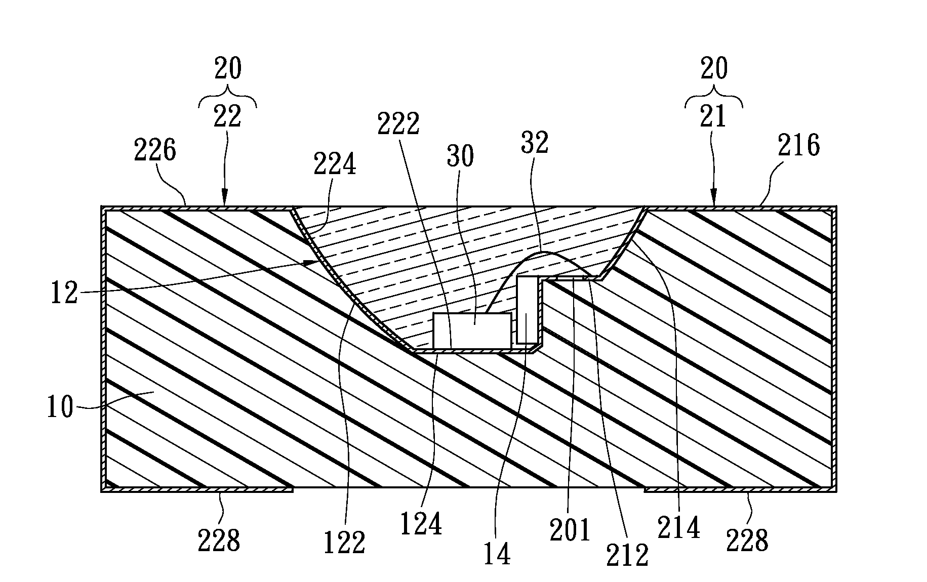
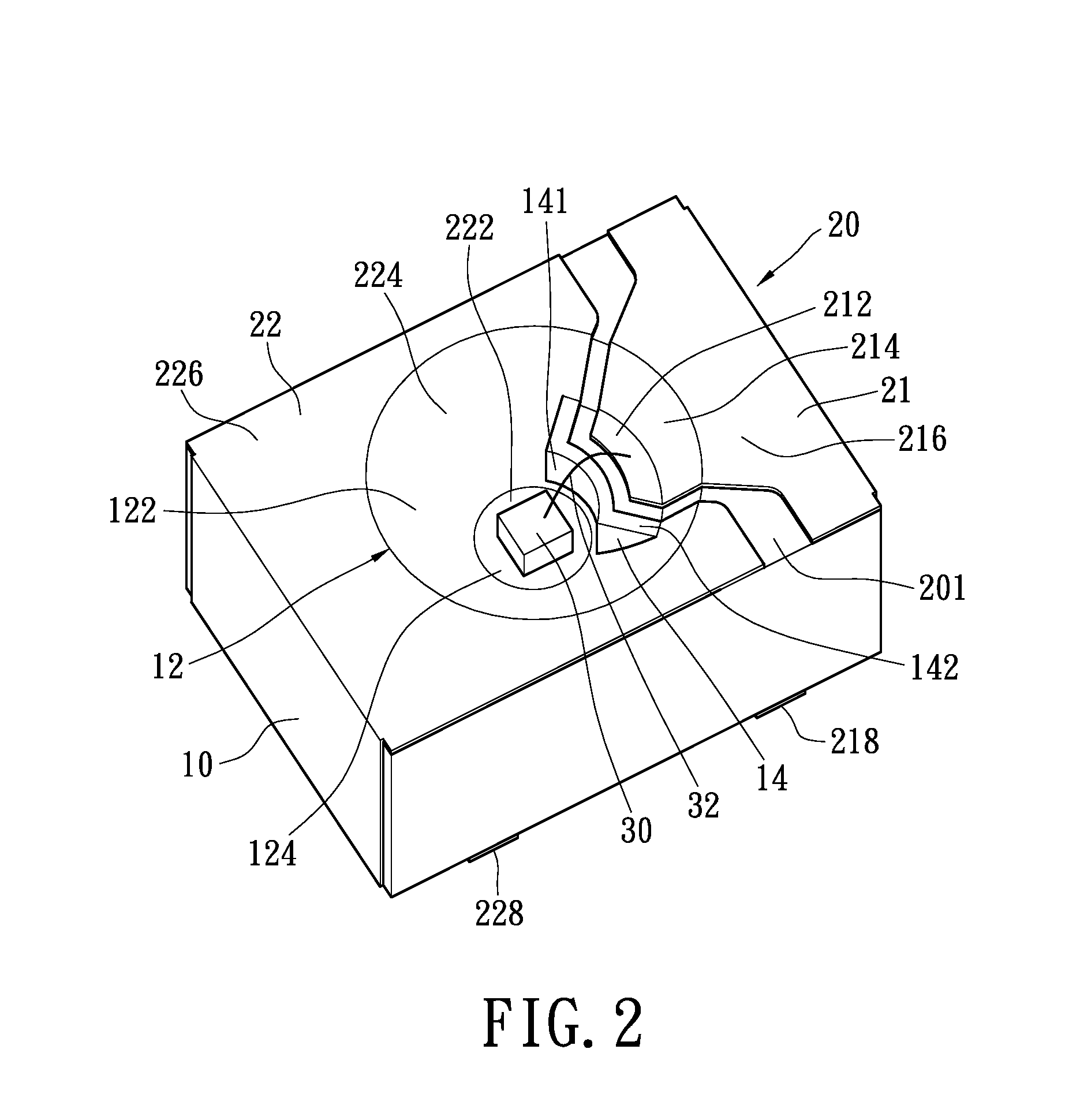
[0023]Reference is made to FIG. 2, which is a perspective view of surface mounted LED package according to the instant disclosure. The structure of the instant disclosure is illustrated in relation to the manufacturing method. A surface mounted LED package of the instant disclosure includes an insulated body 10, a conductive layer 20 formed on a surface of the insulated body 10, a LED chip 30, and a bonding wire 32. The conductive layer 20 is extended to an outer surface of the insulated body 10 (in this embodiment is a bottom surface) to form a first solder pin 218 and a second solder pin 228, so that the instant disclosure could be mounted on the PCB (not shown) by surface mounted technology.

[0024]The insulated body 10 is made of insulating mate...


PUM


Abstract

A surface mounted LED package includes an insulated body, a first conductive part, a second conductive part, a LED chip and a bonding wire. The insulated body has a receiving portion and a bond-pad island. The receiving portion is formed with an inner side wall and a flat bottom. The bond-pad island is formed with a bonding plane. The first conductive part has a LED chip and a first solder pin extended to an outer surface of the insulated body. The second conductive part has a second contacting portion and a second solder pin extended to an outer surface of the insulated body. The LED chip is disposed on the second contacting portion. The bonding wire connects the LED chip to the first contacting portion. The present application further provides a manufacturing method for surface mounted LED package.

Description

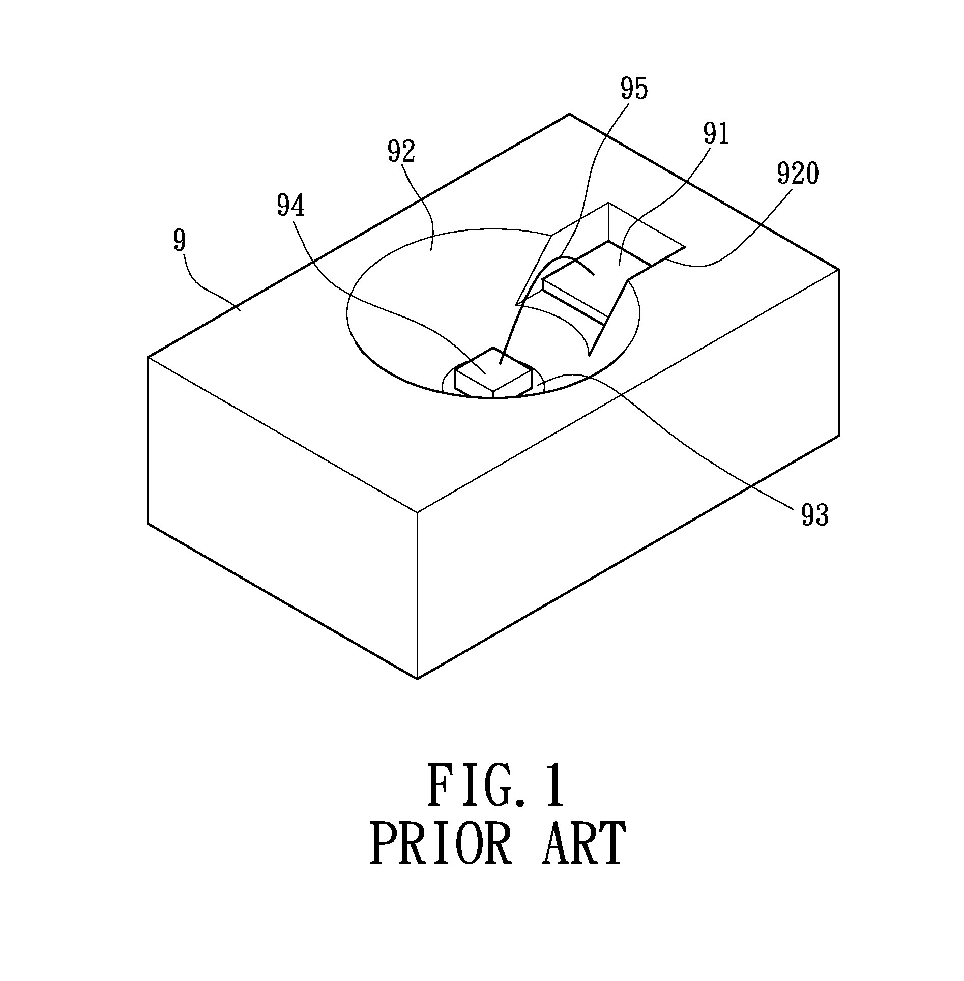
BACKGROUND OF THE INVENTION[0001]1. Field of the Invention[0002]The instant disclosure is related to a surface mounted (SMT) LED package and manufacturing method thereof, especially to an LED package has flatted solder pins and can be soldered on a substrate or PCB by Surface Mounted Technology.[0003]2. Description of Related Art[0004]Surface mounted LED has been popularly used as proximity sensor, which has been applied in mobile phone, TV or portable mobile device for sensing the presence of user. To get a longer detecting distance, the surface mounted LED needs smaller beam angle and higher intensity. Therefore, the surface mounted reflection LED is developed to meet the above-mentioned requirements.[0005]Referring to FIG. 1, a conventional surface mounted LED package has an insulated body 9, which including a bowl-shaped receiving portion 92 and a pad setting area 920 located outside the receiving portion 92. The pad setting area 920 is concaved outwardly and downwardly from an ...

Claims


Application Information

Patent Timeline
Patent Type & Authority Applications(United States)
IPC IPC(8): H01L33/62H01L33/48
CPCH01L33/486H01L33/62H01L2924/3025H01L2224/48227H01L2224/48091H01L2924/00014H01L2924/00
Inventor WANG, YOU-FA
Owner LITE ON SINGAPORE PTE LTD
Learn More