Focus adjustment device and imaging apparatus

a technology of adjustment device and imaging apparatus, which is applied in the direction of focusing aids, instruments, television systems, etc., can solve the problems of time-consuming and difficult adjustment of focus, and achieve the effect of adjusting focus

Active Publication Date: 2013-01-10
NIKON CORP
View PDF4 Cites 37 Cited by
  • Summary
  • Abstract
  • Description
  • Claims
  • Application Information

AI Technical Summary

Benefits of technology

[0032]According to the present invention, it is possible to suitably adjust the focus.

Problems solved by technology

For this reason, in the scenes where either system of the phase difference detection system or contrast detection system could not be used to detect the focus, sometimes the focus could not be adjusted well.
Further, in the above PLT 1, first, the phase difference detection system is used to detect the focus, then the contrast detection system is used to detect the focus, so there was also the problem of the focus adjustment ending up taking time.

Method used


Image

  • Focus adjustment device and imaging apparatus
  • Focus adjustment device and imaging apparatus
  • Focus adjustment device and imaging apparatus

Examples


first embodiment

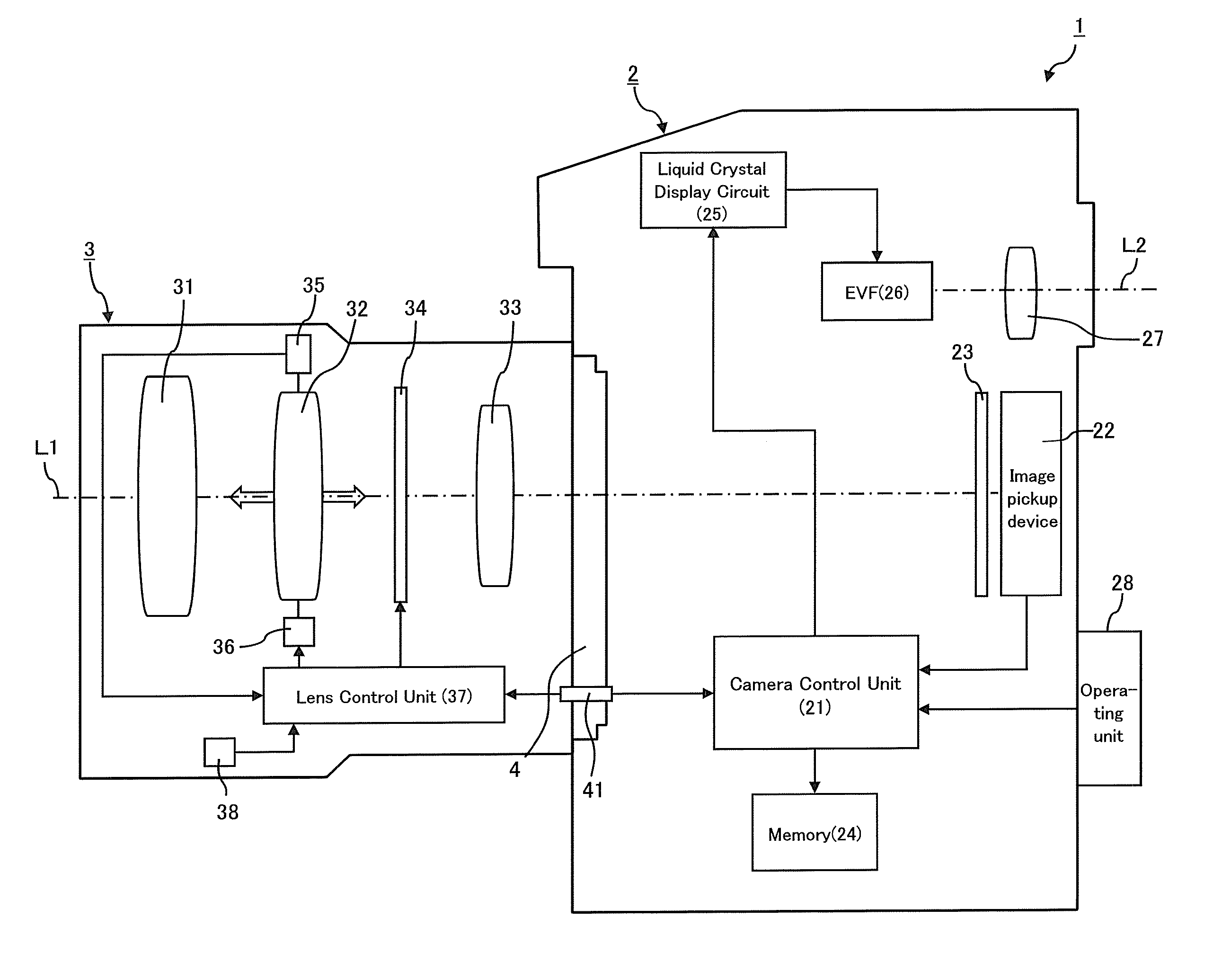
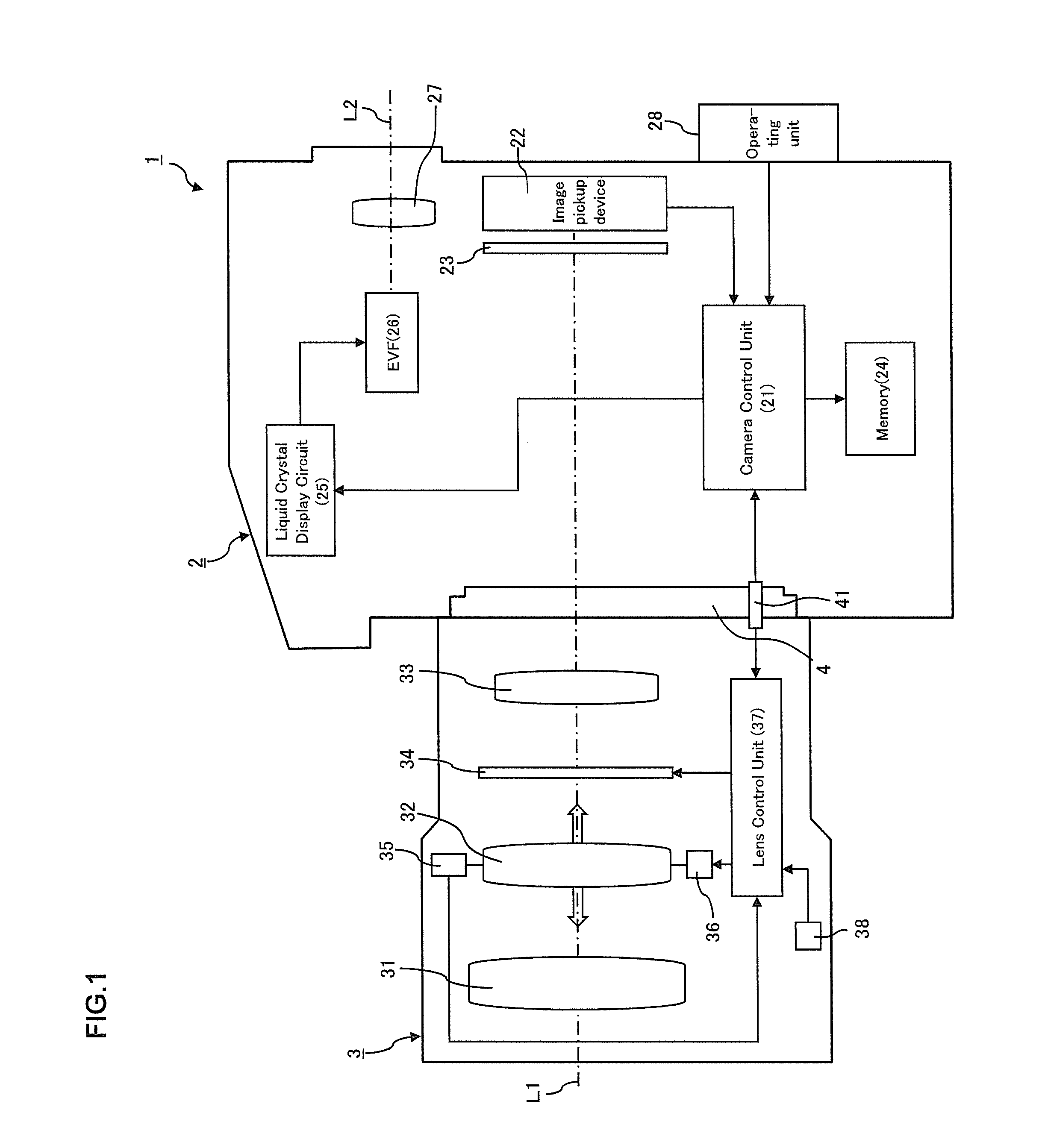
[0052]FIG. 1 is a view of the principal configuration which shows a digital camera 1 according to an embodiment of the present invention. The digital camera 1 of the present embodiment (below, simply referred to as the “camera 1”) is comprised of a camera body 2 and a lens barrel 3. These camera body 2 and lens barrel 3 are connected by a mount 4 in a detachable manner.

[0053]The lens barrel 3 is an interchangeable lens which can be detachably attached to the camera body 2. As shown in FIG. 1, the lens barrel 3 has built into it an imaging optical system which includes lenses 31, 32, and 33 and an aperture 34.

[0054]The lens 32 is a focus lens. By moving it in the optical axis L1 direction, the focal distance of the imaging optical system can be adjusted. The focus lens 32 is provided in a manner movable along the optical axis L1 of the lens barrel 3. An encoder 35 is used to detect its position while a focus lens drive motor 36 is used to adjust its position.

[0055]The specific consti...

second embodiment

[0126]Next, a second embodiment of the present invention will be explained based on the drawings. The second embodiment is similar to the first embodiment other than, as shown in FIG. 14, the operation of the camera 1 in the camera 1 which is shown in FIG. 1. FIG. 14 is a flow chart which shows the operation of the camera 1 according to the second embodiment. Note that, the following operation is started by the power of the camera 1 being turned on and the shutter release button which is provided at the operating unit 28 being half pressed (first switch SW1 on). Further, below, the explanation will be given with respect to the example of the continuous mode, that is, the mode of continuously detecting the focused state of the optical system and thereby capturing an image at a focus lens position corresponding to the object without fixing the position of the focus lens 32, being selected.

[0127]At step S201, in the same way as step S103 of the first embodiment, processing for calculat...

third embodiment

[0147]Next, a third embodiment of the present invention will be explained based on the drawings. The third embodiment is similar to the first embodiment other than, as shown in FIG. 15, the operation of the camera 1 in the camera 1 which is shown in FIG. 1. Below, referring to FIG. 15, the operation of the camera 1 according to the third embodiment will be explained. Note that, FIG. 15 is a flow chart which shows the operation of the camera 1 according to the third embodiment.

[0148]First, as shown in FIG. 15, at step S301, in the same way as step S103 of the first embodiment, the phase difference detection system is used to calculate the amount of defocus. Further, at step S302, the camera control unit 21 is used to judge if the drive of the focus lens 32 based on the results of detection by the phase difference detection system, that is, the drive of the focus lens 32 based on the amount of defocus, is being prohibited. If drive of the focus lens 32 based on the results of detectio...


PUM


Abstract

A focus adjustment device comprising: a first detector 221 which detects a focused state by a contrast detection system; second detectors 222a, 222b which detect a focused state by a phase difference detection system; and a control unit 21 which controls the first detector 221 and second detectors 222a, 222b so as to detect the focused state by the second detectors 222a, 222b when detecting the focused state by the first detector 221.

Description

BACKGROUND OF THE INVENTION[0001]1. Field of the Invention[0002]The present invention relates to a focus adjustment device and an imaging apparatus.[0003]2. Description of the Related Art[0004]In the past, there has been known the art where, when adjusting the focus of an optical system, to improve the precision of the focus adjustment, first, a phase difference detection system is used to detect the focused state of the optical system, the results of detect ion by the phase difference detection system are used as the basis to drive the lens for focus adjustment to near the focused position, then, near the focused position, a contrast detection system is used to detect the focused state of the optical system, and the results of detection by the contrast detection system are used as the basis to drive the focus adjustment optical system to the focused position (for example, see Japanese Patent Publication No. 2004-109690 A1).SUMMARY OF THE INVENTION[0005]However, the above PLT 1 is p...

Claims


Application Information

Patent Timeline
Patent Type & Authority Applications(United States)
IPC IPC(8): H04N5/232
CPCG02B7/36G03B13/36H04N5/23209G02B7/285H04N5/3696G02B7/346H04N5/23212H04N23/663H04N23/672H04N23/673H04N25/136H04N25/134
Inventor TAKAHARA, HIROAKITOMITA, HIROYUKI
Owner NIKON CORP
Why Eureka
Try Eureka