Vehicle headlamp

a headlamp and headlamp technology, applied in the field of headlamps, can solve the problems of difficult control of luminous intensity distribution according to the characteristics of headlamps and daytime running lamps, and achieve the effects of light emission, reduced cost, and space saving

Inactive Publication Date: 2013-01-10
KOITO MFG CO LTD
View PDF3 Cites 20 Cited by
  • Summary
  • Abstract
  • Description
  • Claims
  • Application Information

AI Technical Summary

Benefits of technology

[0010]According to one or more embodiments of the present invention, the optical system for directing light emitted from the first light source which is used, for example, as a DRL or CLL light source towards the lens and the optical system for directing light emitted from the second light source which is used, for example, as a headlamp light source towards the lens are provided separately. Therefore, the luminous intensity distribution can be controlled so as to match each of the objects of the first light source and the second light source. Additionally, the light emitted from the first light source is shone to the front of the vehicle from both the first lens and the second lens, and therefore, the light emitting area when the first light source is illuminated can be expanded. In addition, the two types of lamps having the different objects can be integrated into the single unit, and therefore, it is possible not only to realize a reduction in cost but also to save space.
[0011]The sub-reflector may be disposed near to the rear focal point of the second lens. By so doing, reflected light from the sub-reflector is shone to a position lying near to an optical axis of the second lens, and therefore, an area lying near the horizontal center line can be illuminated brightly when the first light source is turned on.
[0012]An auxiliary reflection member may further be provided which reflects part of light emitted from the first light source towards the sub-reflector. By so doing, the amount of light which is guided to the second lens can be increased more than when light is caused to reach the second lens directly from the first light source. The auxiliary reflection member may be part of one of the other optical components or may be configured as a single optical component.
[0013]A shielding member may further be provided which conceals a gap defined between the first lens and the second lens. By so doing, the external appearance of the vehicle headlamp can be improved by making the internal construction of the headlamp such as the auxiliary reflection member invisible from the outside thereof.

Problems solved by technology

Because of this, a luminous intensity distribution control according to the characteristics of the headlamp and the daytime running lamp may be difficult.

Method used


Image

  • Vehicle headlamp
  • Vehicle headlamp
  • Vehicle headlamp

Examples


first embodiment

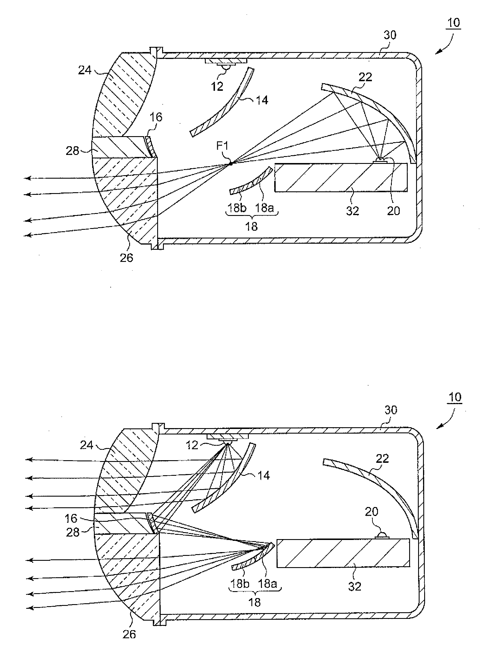
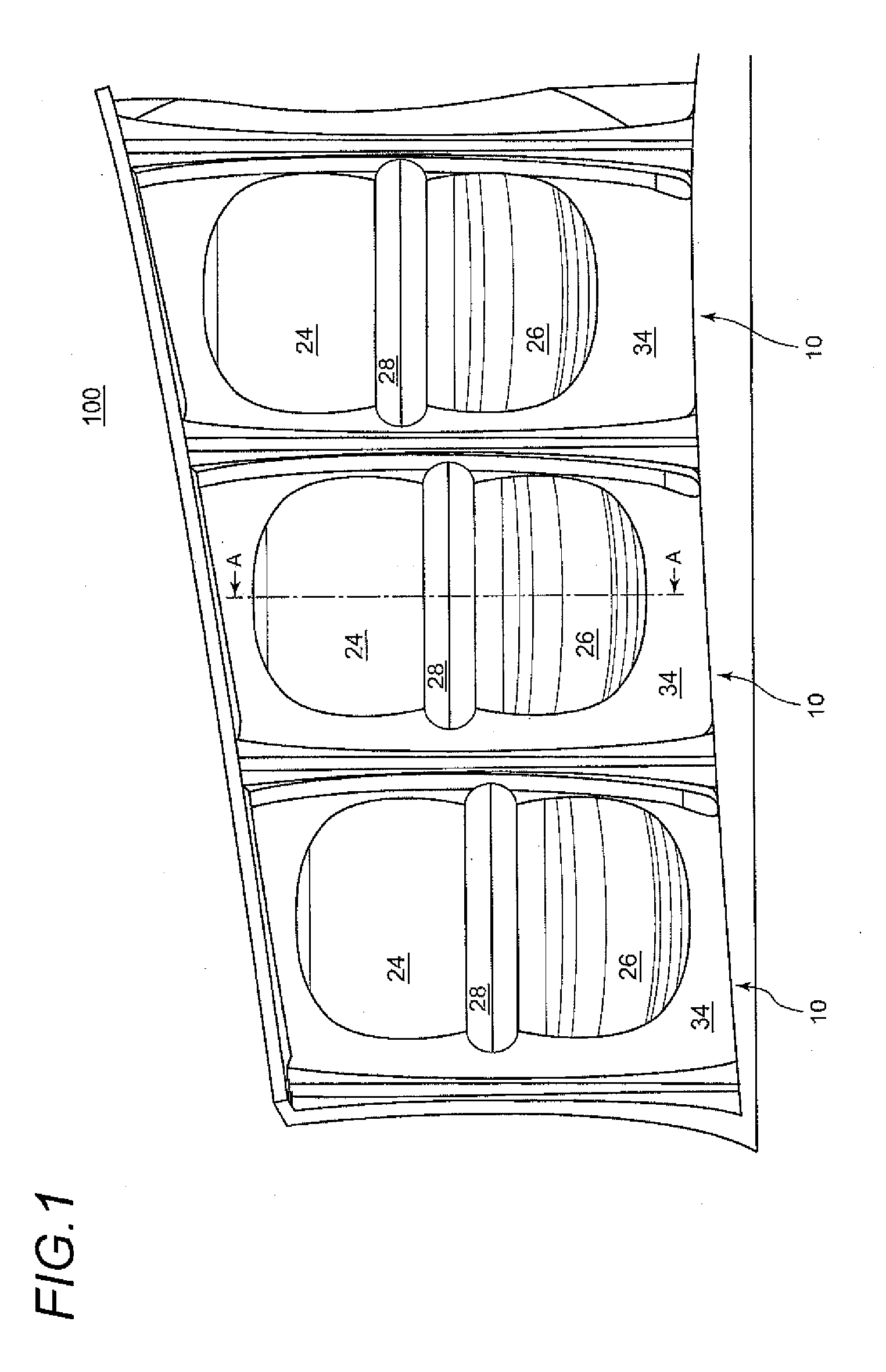
[0023]FIG. 1 is a front view of a headlamp unit 100 into which vehicle headlamps according to the invention are incorporated when a vehicle is seen from a front thereof. The headlamp unit 100 includes three vehicle headlamps 10. Each vehicle headlamp 10 has a DRL lens 24 and an HL lens 26 which are fitted in a cover 34. A shielding member 28 is disposed between the DRL lens 24 and the HL lens 26. The shielding member 28 shields an internal construction of the headlamp such as an auxiliary reflection member 16, which will be described later, from the outside so as to improve the external appearance of the vehicle headlamp when observed from the front of the vehicle.

[0024]As will be described later, the vehicle headlamp 10 includes a light source for a daytime running lamp (DRL) and a light source for a headlamp (HL) which are incorporated in a single unit. Then, by turning on either of the light sources, a luminous intensity distribution pattern for DRL or HL can be formed on an imag...

second embodiment

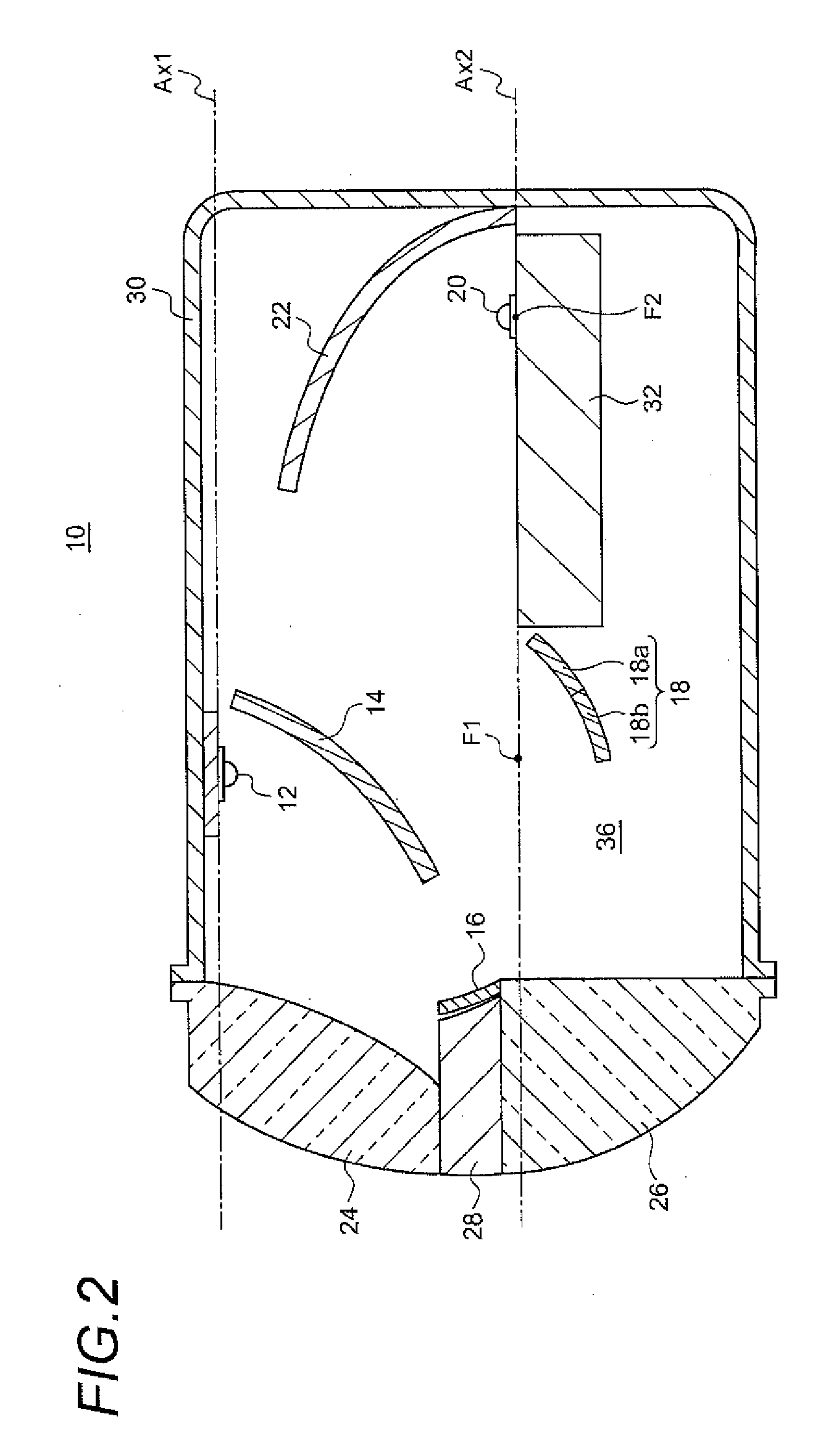
[0053]Thus, as has been described heretofore, also, in the vehicle headlamp the DRL light source and the HL light source are disposed in the same casing, while the optical system for directing light from the DRL light source towards the DRL lens and the optical system for directing light from the HL light source towards the HL lens are provided separately. Consequently, the luminous intensity distribution can be controlled individually for the DRL and the HL by designing the reflection planes of the reflectors therefor to match the objects of the DRL and the HL.

[0054]Additionally, light emitted from the DRL light source is shone to the front of the vehicle from both the DRL lens and the HL lens, and therefore, the light emitting surface resulting when the DRL light source is turned on can be expanded without using any additional light source.

[0055]In addition, the two types of lamps having the different objects can be integrated into the single unit, and therefore, it is possible n...


PUM


Abstract

A vehicle headlamp has a first light source disposed on a first optical axis that extends in a front-to-rear direction of a vehicle, a first lens that projects light emitted from the first light source to a front of the vehicle, a second lens having a rear focal point on a second optical axis that is parallel to the first optical axis and disposed adjacent to the first lens, a second light source disposed on the second optical axis rearwards of the first light source, a reflector that reflects light emitted from the second light source towards the rear focal point of the second lens, and a sub-reflector disposed such that the sub-reflector does not interfere with an optical path which extends from the reflector to the second lens and that causes part of light emitted from the first light source to be incident on the second lens.

Description

CROSS-REFERENCE TO RELATED APPLICATIONS[0001]The present application claims the benefit of priority of Japanese Patent Application No. 2011-149512, filed on Jul. 5, 2011, which is incorporated herein by reference.BACKGROUND[0002]1. Field of the Invention[0003]The present invention relates mainly to a vehicle headlamp.[0004]2. Related Art[0005]There is known a daytime running lamp in which a headlamp is turned on in the daytime to enable the driver of an oncoming vehicle or a pedestrian to visually recognize the existence of the subject vehicle. Although normal headlamps may be turned on as daytime running lamps, there have been developed daytime running lamps which include an exclusive light source.[0006]JP-A-2009-158386 discloses a vehicle headlamp which includes a headlamp light source and a daytime running lamp light source. In this vehicle headlamp, light from the headlamp light source is reflected to the front of a vehicle by a headlamp reflector, while light from the daytime r...

Claims


Application Information

Patent Timeline
Patent Type & Authority Applications(United States)
IPC IPC(8): F21V7/00
CPCF21S48/1154F21S48/1159F21S48/1388F21S48/1258F21S48/1241F21S41/265F21S41/275F21S41/321F21S43/14F21S43/26F21S43/315F21S43/40F21S45/47F21S41/365F21W2102/18F21S41/148
Inventor KOIZUMI, HIROYA
Owner KOITO MFG CO LTD
Why Eureka
Try Eureka