Packaged propellant air-induced variable thrust rocket engine
Active Publication Date: 2013-01-17
INNOVATIVE DEFENSE
7 Cites 3 Cited by
AI-Extracted Technical Summary
Problems solved by technology
Light energy is absorbed but can not be radiated back out of the particle, causing very rapid heating of the particle b...
Benefits of technology
[0022]This combustion produces significant heat and hot steam discharge from the combustion chamber which increases the velocity of the air through a critically angled Venturi combustion flow area. Because the fuel is dispensed in packets and can be ignited on command, the engine will be ca...
Abstract
This invention is a packaged propellant air-induced variable thrust rocket engine that has a vast number of uses and applications for this invention. The primary purpose of the device described here is to provide a light weight, torque and vibration free thrust generator for the propulsion of aircraft. This device will facilitate the fabrication of very light weight aircraft because of the lack these forces. This device can also be used anywhere high velocity air flow and or the resulting thrust is needed. The invention uses aerodynamic principles to compress and accelerate the incoming air, prior to it being heated and accelerated by a short duration burst of thermal and kinetic energy from discrete packets of a mixture of oxidizable fuels. The heated and accelerated air then expands as it travels thru the device providing thrust.
Application Domain
Rocket engine plantsPressure gas generation
Technology Topic
AirplaneAerodynamics +4
Image
Examples
- Experimental program(1)
Example
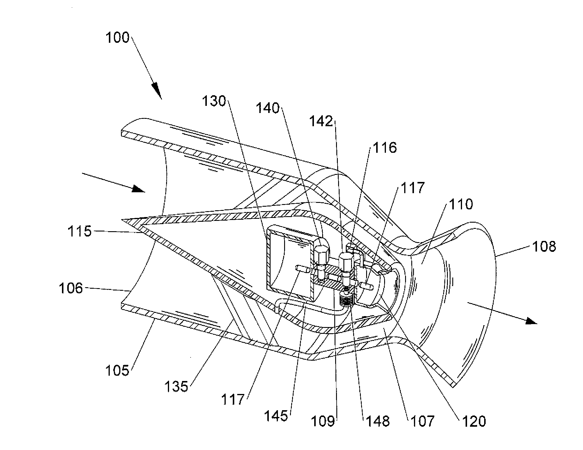
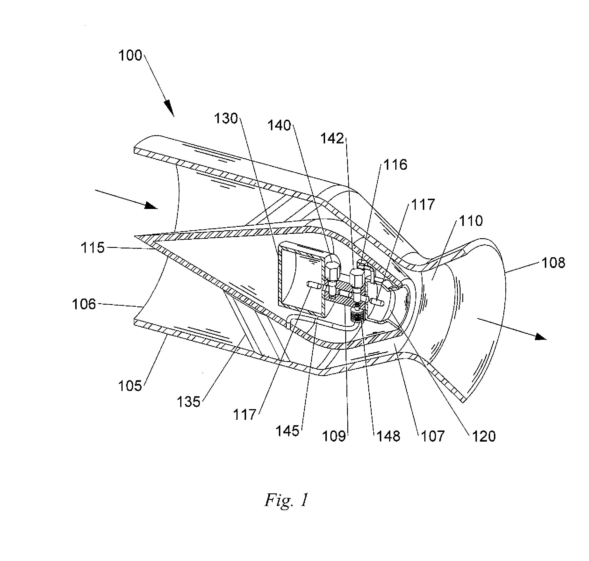
[0023]FIG. 1 shown an air-induced rocket engine 100 using the teachings of the present invention. Air enters through front airflow inlet 106 and is divided by a central air divider 115 which supported in the airflow housing 105 by support struts 135. Located inside the central air divider 115 is an Energetic Fuel Packet (EFP) 117 storage compartment 130. This storage compartment can be replaced or supplemented by a separate storage area located outside the housing 105 with a connecting delivery tube not shown.
[0024]When thrust is needed, a backflow prevention valve 140 opens and an EFP 117 is injected through the air/fuel delivery manifold 109 into the combustion chamber 120. Photonic energy from a strobe light 116 or other means ignites the nano-aluminum particles contained in the water and the EFP 117, while in the combustion chamber 120. Very high temperature is created by the nano-energetic particles that convert the surrounding water to superheated steam, and also igniting other combustibles in the EFP 117.
[0025]A percentage of hydrogen peroxide can be included in the EFP 117 to provide more oxygen for oxidation. The water also prevents the temperature from rising to a level that would require refractory materials in the combustion chamber 120. Having a short duration burn with a controlled temperature rise transfers more of the thermal energy into the accelerating the air flow, instead of waste heating the walls of combustion chamber 120. This produced high temperature steam expands directionally from the combustion chamber 120 at high velocity into the Venturi combustion flow area 110.
[0026]This causes the air in the Venturi combustion flow area 110 of the airflow housing 105, to increase in temperature, drop in density and flow aft through the Venturi combustion flow area 110. The aft flow is caused by the velocity of the steam and heated air mix. After the pressure impulse has dissipated, air flush valve 142 allows air to flow thru air inlet passage 145 from the higher pressure region on the divider 115 into the air/fuel delivery manifold 106 and the attached combustion chamber 120 transferring residual heat to the Venturi combustion flow area 110 and providing fresh air for the next EFP 117 ignition.
[0027]The higher density and pressure of the colder incoming air fills the low pressure volume created by the high velocity movement of the mixture through the Venturi combustion flow area 110. Since the expanding steam has a slightly lower density than the air, as it expands into the Venturi combustion flow area 110 it gives up heat to the air in the path thusly increasing the enthalpy of air. In this process the relative humidity of the air rises as heating occurs creating a higher enthalpy and less dense air steam mixture which must expand as its density drops creating more velocity. This method of heat transfer is more effective than the heating and drying of air in a traditional turbine.
[0028]The humidified air steam mixture has a lower exit temperature while it expands and moves aft out rear exhaust 108, it is then replaced by colder more dense incoming air entering the annulus flow area 107. After all available heat is transferred another EFP 117 moves from the storage area 130 into the combustion chamber 120 and the cycle continues. The rapidity with which the EFPs 117 are dispensed and ignited determines the air velocity, mass flow rate and thrust of the device.
[0029]The directionality and design of the combustion chamber 120 and its location relative to the Venturi combustion flow area 110, prevents the high pressure thermal steam front from creating backpressure in the annulus flow area 107, even at zero velocity of the incoming air. The rapidly moving air steam mixture causes a pressure drop across the annulus flow area 107, due to its velocity and low density. This drop in pressure causes air to flow in the air housing 105, from front inlet 106 to rear exhaust 108 through the Venturi combustion flow area 110.
[0030]The velocity of the air is a function of the temperature and speed off the expanding thermal front from the input of energy of the EFP 117 in the combustion chamber 120. These velocities could be 2 k/s or greater providing sufficient thrust for vertical or horizontal flight. The humidified and heated air travels thru Venturi combustion flow area 110 and expands rearward thru the rear expanding nozzle 108 before exhausting the thruster.
[0031]In certain applications this device 100 or multiples of device 100 could be surrounded by an outer air housing through which air is drawn in, heated by the external heat of the thrusters and exhausted at higher velocity, giving extra thrust. This flow of cooler air can provide cooling to the thruster and reduces or eliminates the heat signature. It is a design intention to avoid high combustion and gas temperatures inside the engine to allow lightweight materials to be used. This is facilitated by using direct fuel to water contact which produces steam as well as other exhaust components to transfer the fuel energy to the air flowing thru the thruster.
[0032]The EFPs 117, can have various amounts of energetic nano-aluminum and other fuels, to further allow the device to provide variable thrust on demand. This type of engine would be most desirable in a combat situation because its lack of continuous heat signature and sound, which can be dampened or eliminated. At cruise power levels, the intermittent operation allows the exhaust to be close to atmospheric conditions. This thruster has no rotating masses as a consequence it can sustain many penetrations from small arms or bomb fragments and still operate.
[0033]In a vertical takeoff situation, where very high thrust power is needed, the temperature control offered by the water allows the needed levels of fuel to be added with sufficient water and flashed to steam providing more thrust which draws additional air through the Air Housing 105, providing extra lift. There are no moving parts in air stream of this thruster just the mechanisms delivering the EFPs 117. Using nanometer-sized aluminum to initiate combustion of other fuels offers many advantages over other means of using liquid fuels.
[0034]These packets can be ignited with high intensity light or other non contact means. Nano-aluminum has 46% more energy than liquid fuels such as gasoline and is only one third the volume by weight. Dispensing fuel in packaged form allows for pulsed operation in this device. In a combat zone this would allow an aircraft to quietly swoop on an enemy unheard in a glide mode and have the ability to add power only when needed. Additionally by design the sonic energy assists the acceleration of the exhaust air and is focused behind the aircraft along the axis of travel, so little sound is projected ahead of the aircraft.
[0035]Produced sound is intermittent as well and at a low frequency compared to modern aircraft engines with noise signature audible for tens of miles. All of the materials in the fuel packets contain energy which will be consumed in the combustion process and that energy extracted leaving no visible or thermal signature. Nano Al packages can be used as an ignition source in combination with conventional fuels to power this or other devices. The timing between initiations needs to be long enough for all of the heat of the prior combustion to be used and the airflow into Venturi combustion flow area 110 have time to establish a stable air pressure.
[0036]In this way, all of the energy is used to propel the air backward and not on pulling in air to annulus flow area 107 as would happen in a continuous burn condition where the inlet pressure at Venturi combustion flow area 110 drops. Ideally the thruster is sized to be able to operate most efficiently except at max power intervals such as takeoff or maneuver. During these high power periods this design is capable of very high thrust outputs due to the design of combustion chamber 120. An optional air compressor 148 can be added to boost air flow in air tube 145 in applications where the interval between firings is insufficient to allow unassisted replenishment of air in combustion chamber 120.
[0037]This device can also be used wherever high speed air flow is needed. This is not limited to but could include blowing out fires, clearing runways, excavating earth, drying up mud or water, finding buried objects, crowd control, takeoff booster engines and others. This device could be used on a remote operated vehicle for blowing away loose dirt and uncovering land mines and other objects. This device could be used outside the atmosphere if it were fitted with shutters on the intake and steam used as the mass exchange fluid. Very little water would be required in the vacuum of space, even the waste water from the occupants of the spacecraft could be used. This particular spike design has more rapid acceleration of air than the free flow design shown in FIG. 2 but has a lower max thrust.
[0038]FIG. 2 is a high air flow modified rocket with Venturi combustion flow area device 200, which offers easy flow during non heating periods for more efficient heat transfer as the air enters at entrance 201 of main flow air housing 205 and travels without constriction through the device past a cluster of combustion chambers 240 arrayed around the combustor mounting ring 208. These combustion chambers 240 are supplied with Energetic Fuel Packets (EFP) 230 that are stored in dispenser 235 and travel through a delivery air/fuel delivery manifold 220 which is equipped with a back flow prevention valve 215 to prevent hot gases and bright light from traveling back up the delivery air/fuel delivery manifold 220 to dispenser 235.
[0039]During periods of non-combustion, an air flush valve 218 is open to allow air flow into the combustion chamber 240 to remove heat and provide air for the next combustion. Depending on the power requirements this air may be from air flow in the outer casing or provided by a pressurized air source. The combustor assembly is equipped to swivel on slide 225 to alter the angle 270 of the combustion chamber axis 275 relative to the housing axis 280. At initial startup and during low speed operation the combustion chambers 240 are at a minimum angle for initial startup while the air coming thru inlet 201 has little or no velocity. During periods of no combustion, air flowing through the main flow air housing 205 at Venturi combustion flow area section 210 is mostly undisturbed and maintains laminar flow depicted by the unbent stream lines 250 until exiting the tube at 215.
[0040]In FIG. 2A, the combustion chambers 240 are shown firing at a minimum angle φ270 for startup or low speed operation. During startup the air inside Venturi combustion flow area section 210 is not moving, the angle φ270 of combustion chamber 240 ensures that there is not unproductive backflow. When combustion of an energetic fuel packet 230 has initiated, combustion chamber 240 creates a pressurized flow out of the exhaust port 245 along the trajectory shown by arrow 255.
[0041]This burning heated exhaust deflects and heats the air inside the Venturi combustion flow area section 210, simulating a narrower orifice, shown by the slightly bent streamlines 260. The fuel burning in the combustion chamber 240 also produces superheated steam to propel the heated and possibly still burning mixture along the desired trajectory in Venturi combustion flow area section 210. The pressure and flow created by the superheated steam eliminates the need for high pressure injection pumps and supporting power units.
[0042]Thrust from this device is obtained by introducing the thermal energy of the energetic fuel packet 230 as a pressurized thermal wave. These thermal waves, emanating from individual combustion chambers 240, arranged around the perimeter of a air housing 205, converge at the center of Venturi combustion flow area section 210 of the main flow air housing 205 creating a virtual Venturi system. As these flow streams 260 converge, a Mach Stem is formed accelerating the converged front up to 6 times its input velocity, depending on the convergence angle.
[0043]In FIG. 2B, the combustion chambers 240 of the modified rocket engine is shown having at a greater angle φ2 285 than angle 270 in FIG. 2A to the air housing axis 280. This greater angle φ2 285 is needed during high velocity air flow to create the virtual Venturi combustion flow area reduction. As shown in FIG. 2A combustion of a energetic fuel packet 230 that has initiated in combustion chamber 240 creating pressurized flow out of the exhaust port 245 along the trajectory shown by arrow 255.
[0044]This burning heated exhaust deflects and heats the air inside the Venturi combustion flow area section 210, simulating a narrower orifice, shown by the bent streamlines 265. Since the fuel is initially burned in the combustion chamber 240 prior to being introduced into the air stream in Venturi combustion flow area 210. The greater the angle 285 the faster the Mach Stem, this offers an advantage at higher airspeeds by allowing the thermal wave to be introduced at a less oblique angle to the axis of flow depicted by arrow 255. This would facilitate a more concentrated impulse and a more rapid acceleration of the air mass.
[0045]The rapidly increased flow is achieved because the convergence angle of the thermal front is more acute, thusly causing the cone shaped air mass formed by the front, to achieve a higher velocity. There are a range of advantageous angles 285 possible that are dependent on air flow velocity, a greater combustion chamber 240 angle 285 is possible with higher air velocity moving through Venturi combustion flow area 210.
[0046]By introducing the energy from the energetic fuel packet 230 in this manner a greater amount of heat energy or enthalpy is added to the incoming air. The circumferentially converging thermal front provides a much greater area of contact with the air than fuel ignited in the moving air stream and is far more efficient. Since the incoming air is directed inward and away from the wall of the air housing 205 there is less thermal stress on the air housing 205.
[0047]These waves could move at 2 k/s or greater depending on the fuel or combinations of fuels used. The direction of this thermal wave is controlled by increasing or decreasing angle 285. The combustion chambers 240 axis 275 could be adjustable to take advantage of the Mach Stem increase in velocity at higher airspeeds while serving as a means of eliminating the possibility of backpressure at low or zero air inlet velocity. This ability and the fact that the fuel in this application is initially burned in the combustion chamber 240 and not in the airflow area 210 is what allows time for the fuel to complete a stoichiometric burn before being carried away by the air housing 205 air stream. Fuel processed this way insures that all energy will be extracted from the fuel packet for the purpose of moving air rather than wasted in the exhaust heat.
[0048]Mixtures of fuels can be used in this device such as Methane, Propane, Kerosene or JP5 and many others. The ability to initiate a burn front in Nano sized aluminum (nano-Al) agglomerations by photonic means makes this possible. Since the nano-Al fuel packets are delivered incrementally this air moving device has instant on and off operation capability. Another great advantage of this invention is its lack of moving, parts, as a result of this there are no torque or vibration stresses produced during operation. This facilitates lighter airframes and consequently all parts of the aircraft can be of a much lighter construction.
[0049]FIG. 3 is a cognitional cutaway prospective view of an exemplary energetic fuel packet. The clear outer casing 310 holds the mixture 305 of nano-Al particles 320 in a water or water hydrogen peroxide slurry mixture 305. Suspended in the mixture 305 can be additional fuels such as larger aluminum particles 315, and other fuels. A thin filmed sealed aluminum capsule 330 can be used that may have nano-Al initiators 335 along its length, to ignite it and the hydrocarbon and oxygen mixture 340 that is contained inside. One end of the aluminum capsule 330 can have a combustible plug 325 that has a dual purpose to seal the opening and facilitate the filling of capsule 330 with mixture 340. The combustible plug 325 can be designed to burn more quickly than the initiators 335 or instead of them in applications where it is desired to have capsule 330 move out of the initial combustion area before it is completely oxidized.
[0050]FIG. 3A shows a radical cutaway prospective view of the energetic fuel packet. These waves could move at 2 k/s or greater depending on the fuel or combinations of fuels used. The direction of this thermal wave is controlled by increasing or decreasing angle 285. The combustion chambers 240 axis 275 could be adjustable to take advantage of the Mach Stem increase in velocity at higher airspeeds while serving as a means of eliminating the possibility of backpressure at low or zero air inlet velocity. This ability and the fact that the fuel in this application is initially burned in the combustion chamber 240 and not in the airflow area 210 is what allows time for the fuel to complete a stoichiometric burn before being carried away by the air housing 205 air stream.
[0051]Fuel processed this way insures that all energy will be extracted from the fuel packet for the purpose of moving air rather than wasted in the exhaust heat. Mixtures of fuels can be used in this device such as Methane, Propane, Kerosene or JP5 and many others. The ability to initiate a burn front in nano-sized aluminum (nano-Al) agglomerations by photonic means makes this possible. Since the nano-Al fuel packets are delivered incrementally this air moving device has instant on and off operation capability. Another great advantage of this invention is its lack of moving, parts, as a result of this there are no torque or vibration stresses produced during operation. This facilitates lighter airframes and consequently all parts of the aircraft can be of a much lighter construction.
[0052]Many different capsule 330 configurations can be used with different mixtures 340 and designs to meet usage goals. Capsules such as 330 offer a longer burn time in larger engines such as might be used in a lighter than air vessel, which operates at a low airspeed, or during high power operations. The use of different composition packets 300 to meet the needed power level allows very rapid thrust changes. It will be understood that this example energetic packet does not restrict the variations that are needed to fully implement the advantages of this fuel delivery system component of the invention.
[0053]Furthermore in some below freezing applications the use of frozen water and nano-Al as an outer casing may offer advantages in high altitude aircraft where packets may be fabricated as used with differing compositions. Likewise an outer casing 310 may have a similar design to capsule 330 with an oxidizable metallic shell.
[0054]Another advantage of these thrusters is they can be part of the structure of the aircraft providing further weight and cost savings, since they are inexpensive to build and can be recycled or discarded when no longer serviceable. The weight of this device is approximately 10% of a conventional gas turbine engine of the same diameter. That same reduction in weight could be expected throughout an air craft structure using this novel thrust producing concept because of the reduction of engine weight, and lower structure vibration and stress forces.
[0055]While this thruster can be used to power conventional aircraft designs, it offers great opportunity for innovative new aircraft designs that operate much more efficiently. Likewise it offers new capability in many other applications needing air movement or thrust. In the case of lighter than air vehicles, this type of thrust producing device is ideal because it can be operated in a selectable pulse mode and thrust is not required to provide lift for the craft. This device being capable of pulsed operation in an air buoyant craft allows such a craft to loiter quietly over a location for a very long duration using only sufficient fuel to maintain its position.
[0056]Besides its use for winged aircraft or rocket propulsion, the lack of weight and forces from torque and vibration make this an ideal propulsion system for lighter than air use. Lighter than air craft could be built around the cylindrical strength and rigidity of this engine and would have a very small frontal area. This would facilitate low drag and a negligible radar cross section, all of these attributes of this device make it a combat necessity. The structural integrity of a cylinder, which is the main structure of this device, makes this thruster an imminent candidate for a completely new family of large light weigh aero dynamic craft.
[0057]While a cylindrical shape offers many advantages other configurations are possible, even using many small combustors along the leading edge of an airfoil to accelerate and expand the air traveling underneath it, creating buoyancy. While the invention has been particularly shown and described with respect to preferred embodiments, it will be readily understood that minor changes in the details of the invention may be made without departing from the spirit of the invention. Having described the invention, we claim:
PUM


Description & Claims & Application Information
We can also present the details of the Description, Claims and Application information to help users get a comprehensive understanding of the technical details of the patent, such as background art, summary of invention, brief description of drawings, description of embodiments, and other original content. On the other hand, users can also determine the specific scope of protection of the technology through the list of claims; as well as understand the changes in the life cycle of the technology with the presentation of the patent timeline. Login to view more.
Similar technology patents
Control method for rectifier of switching converters
Owner:STMICROELECTRONICS INT NV
Vacuum cleaner with a divider
Owner:OMACHRON INTPROP
System and Method for Transmitting and Receiving Control Channels
Owner:FUTUREWEI TECH INC
Classification and recommendation of technical efficacy words
- increase efficiency
- increase air velocity
Shingle system and method
Owner:SUNPOWER CORPORATION
Fish and plant factory
Owner:OBRIEN & GERE ENGINEERS
Ring insert for an air intake conduit for an internal combustion engine
InactiveUS7942139B1increase air velocitydecrease air pressure
Owner:MILE EDGE PLUS
Gas directing system and method
ActiveUS20050072393A1increase horsepowerincrease air velocity
Owner:NOW LEO
Screening machine for water conservancy projects
InactiveCN107639024Aincrease air velocityImprove discharge efficiency
Owner:孙宇翔