
Wave activated power generator

Inactive Publication Date: 2013-01-17
BODY FOR GYEONGJU UNIV EDUCATION & IND COOPERATION
View PDF1 Cites 1 Cited by
  • Summary
  • Abstract
  • Description
  • Claims
  • Application Information

AI Technical Summary

Benefits of technology

The present invention provides a solution to problems that previously existed.

Problems solved by technology

Thus, this method has a complicated structure and undergoes difficulty in maintenance and repair.
However, the weight of a chain secured at one end thereof to the anchor and at the other end to the floating body disturbs upward motions of the floating body caused by waves, thereby reducing the vertical shifting amount of the floating body.
Further, since the anchor is secured to a concrete structure placed in the sea bed, it is considerably slow and difficult for workers to move the resonance-type wave power generator to land or a ship for maintenance and repair thereof or to transfer for installation to a place with big waves from a place with tiny waves.

Method used


Image

  • Wave activated power generator
  • Wave activated power generator
  • Wave activated power generator

Examples


Embodiment Construction

[0019]Embodiments of the present invention will be described with reference to FIGS. 1 to 4.

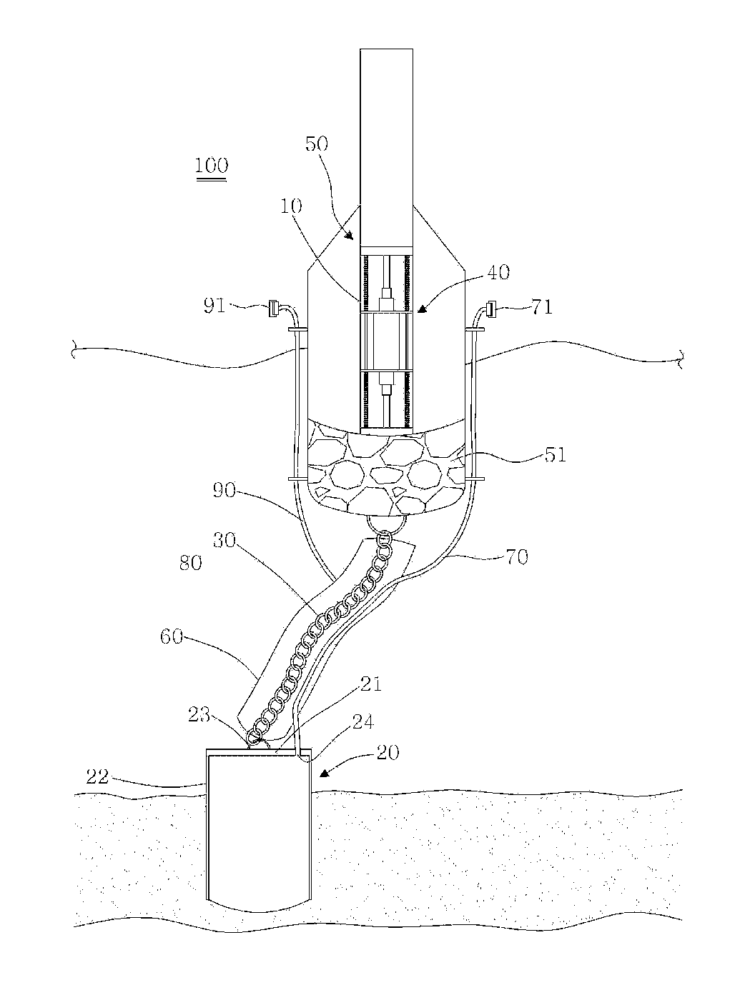
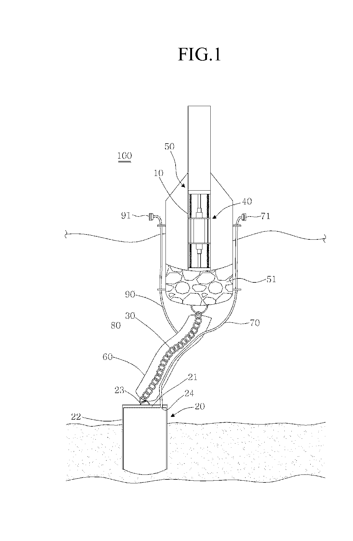
[0020]Referring to FIG. 1, a wave activated power generator 100 according to an embodiment includes a case 10, which sealingly accommodates a power generation unit 40 for generating power by generating induced electromotive force in a coil through relative movement of a permanent magnet and the coil, a floating body 50 enclosing a lower portion of the case 10 while exposing an upper portion of the case 10, a pile 20, and a chain 30 secured at opposite ends thereof to the floating body 50 and the pile 20, respectively.

[0021]The floating body 50 generally has a tumbler shape and includes a mass 51, which is inserted into a lower portion of the floating body 50 to have a center of gravity at a center of a bottom of the floating body 50.

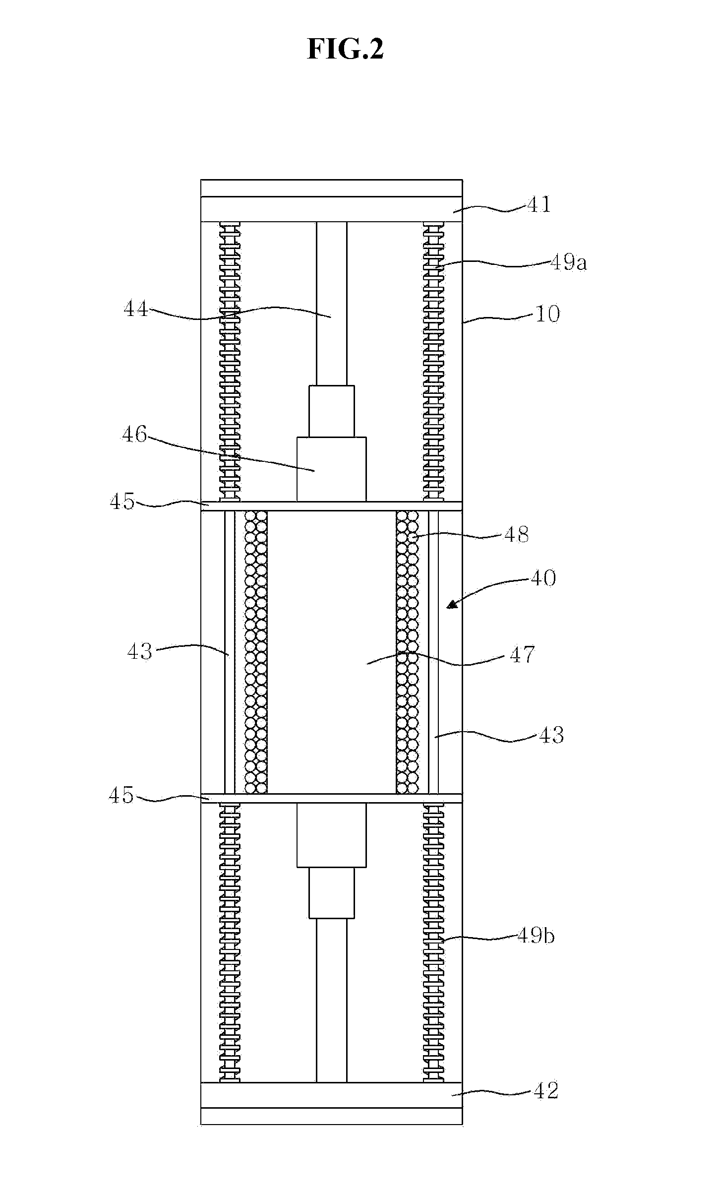
[0022]Referring to FIGS. 1 and 2, the power generation unit 40 includes an upper disk 41 securely inscribed in an upper end of the case 10, a lower disk 42 secure...


PUM


Abstract

The present invention relates to an improved wave activated power generator. The power generator includes a pile, a chain secured at opposite ends thereof to the pile and a floating body, respectively, a suction pipe communicating at one end thereof with an interior of the pile and secured at the other end thereof to the floating body to be exposed from a sea surface, and an air supply pipe connected at one end thereof to an upper end of the tube to communicate with a tube and secured at the other end thereof to the floating body to be exposed from the sea surface. The chain is sealed and surrounded with the tube filled with air. The suction pipe is disposed to pass through the tube.

Description

CROSS-REFERENCE TO RELATED APPLICATION[0001]This application claims the benefit under 35 U.S.A. §119 of Korean Patent Application No. 10-2011-0069031, filed on Jul. 16, 2011 in the Korean Intellectual Property Office, the entirety of which is incorporated herein by reference.BACKGROUND[0002]1. Technical Field[0003]Exemplary embodiments of the present invention relate to a wave activated power generator and more particularly to a wave activated power generator which highly efficiently converts wave energy into electric energy.[0004]2. Description of the Related Art[0005]There are two ways of generating power using wave energy. In a first method, a wave power generator is constituted by interposing a permanent magnet and a coil between two floating bodies which move relative to each other. In a second method, a wave power generator includes a mass inserted into a single floating body with a permanent magnet and a coil interposed between the mass and the floating body which move relati...

Claims


Application Information

Patent Timeline
IPC IPC(8): F03B13/16
CPCF03B3/16F03B13/1845Y02E10/38Y02E10/223F03B13/187F05B2220/707Y02E10/20Y02E10/30F03B13/14F03B13/18F03B17/02
Inventor KWEON, HYUCK-MINKWON, OH-KYUNLEE, JUNG-LYULPARK, SANG-SHINCHO, IL-HYOUNG
Owner BODY FOR GYEONGJU UNIV EDUCATION & IND COOPERATION
Learn More