Spark plug

a technology of spark plugs and plugs, applied in spark plugs, basic electric elements, electric devices, etc., can solve problems such as breakage resistance, and achieve the effect of improving the breakage resistance of an insulator

Active Publication Date: 2013-01-17
NGK SPARK PLUG CO LTD
View PDF2 Cites 23 Cited by
  • Summary
  • Abstract
  • Description
  • Claims
  • Application Information

AI Technical Summary

Benefits of technology

[0005]The present invention has been conceived to solve the above-described problem, and an object of the pr...

Problems solved by technology

In the thus-miniaturized spark plug, since the insulator also has a sm...

Method used


Image

  • Spark plug
  • Spark plug
  • Spark plug

Examples


first embodiment

A. First Embodiment

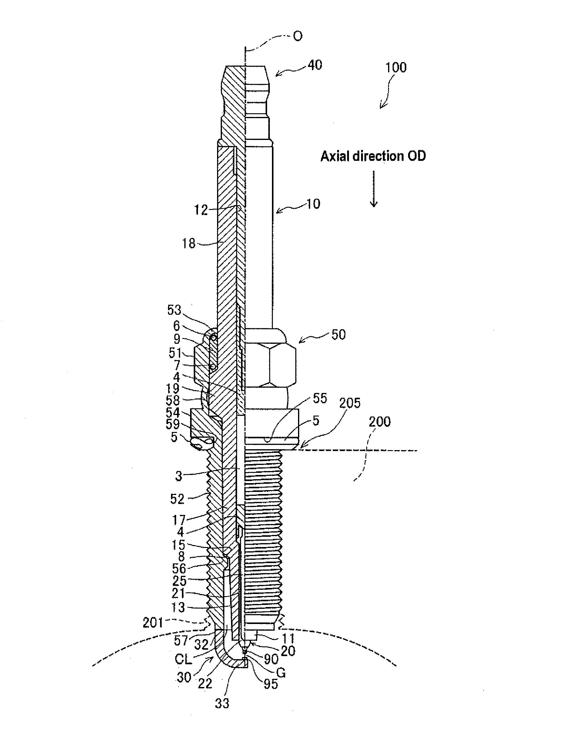
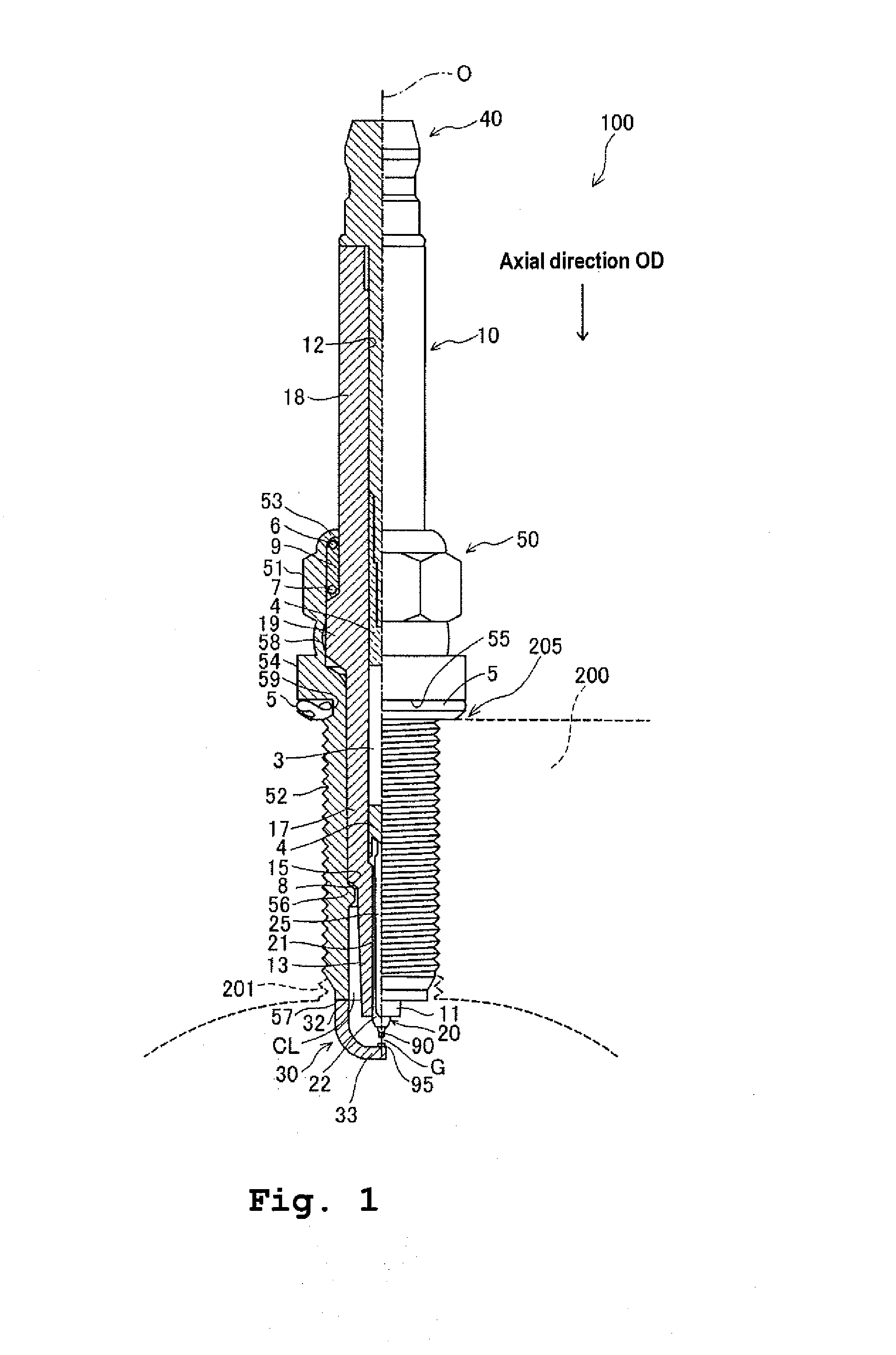
[0064]FIG. 1 is a partially sectional view of a spark plug 100 according to an embodiment of the present invention. In the following description, an axial direction OD of the spark plug 100 in FIG. 1 is referred to as the vertical direction, the lower side of the spark plug 100 in FIG. 1 is referred to as the front end side of the spark plug 100, and the upper side as the rear end side.

[0065]The spark plug 100 includes a ceramic insulator 10, a metal shell 50, a center electrode 20, a ground electrode 30, and a metal terminal 40. The center electrode 20 is held in the ceramic insulator 10 while extending in the axial direction OD. The ceramic insulator 10 serves as an insulator, and the metal shell 50 holds the ceramic insulator 10. The metal terminal 40 is mounted to the rear end portion of the ceramic insulator 10.

[0066]The ceramic insulator 10 is formed from alumina, etc. through firing and has a cylindrical tubular shape, and its axial bore 12 extends coaxiall...

second embodiment

B. Second Embodiment

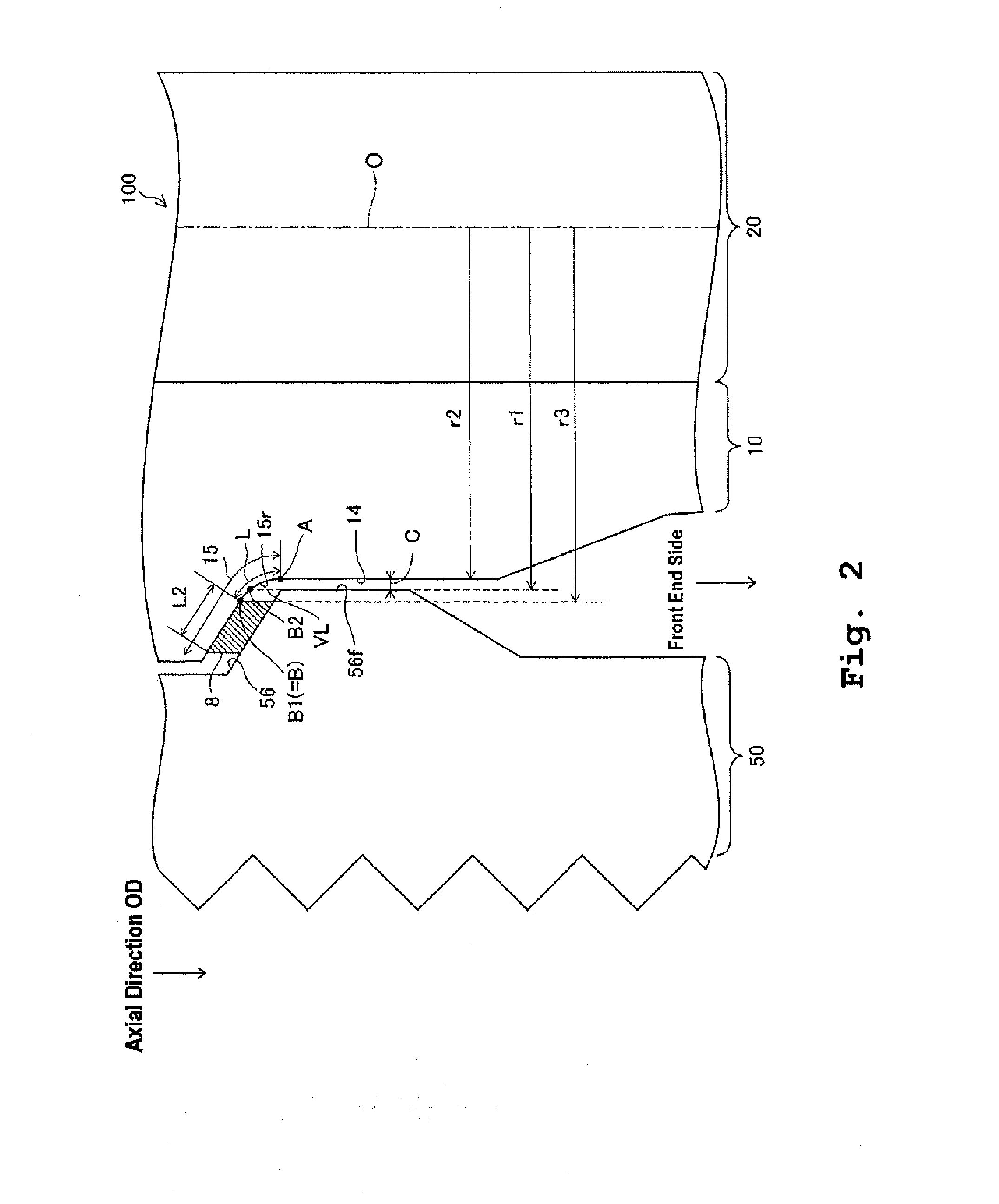
[0094]FIG. 3 is an enlarged view of a support portion 15b of a ceramic insulator 10b of a spark plug 100b according to a second embodiment. Difference to the first embodiment shown in FIG. 2 is only the shape of the ceramic insulator 10b. Other composition of spark plug 100b is the same as that of the first embodiment. The ceramic insulator 10b does not have the curving portion 15r at the front end side of the support portion 15b, and the support portion 15b is formed linearly. When the spark plug 100b without the curving portion 15r satisfies the relationship (2), improvement in breakage resistance of the ceramic insulator 10b is attainable.

third embodiment

C. Third Embodiment

[0095]FIG. 4 is an enlarged view of a support portion 15c of a ceramic insulator 10c and its surrounding in a spark plug 100c according to a third embodiment. Difference to the first embodiment shown in FIG. 2 is shapes of the ceramic insulator 10c and the sheet packing 8. Other composition of the spark plug 100c is the same as that of the first embodiment. The ceramic insulator 10c does not include the curving portion 15r at the front end side of the support portion 15c. Frontward of the support portion 15c with respect to the point B1 is bent. Further, a radius r3 of the inner circumference of the sheet packing 8 is equal to the radius r1 of the inner circumference of metal shell shelf 56f. Thus, the point “B” serves as a point where the point B1 matches with the point B2. When the spark plug 100c without the curving portion 15r satisfies the relationship (2), improvement in breakage resistance of the ceramic insulator 10c is attainable.

D. Experiment

D1. Experime...


PUM


Abstract

A spark plug having an insulator with improved breakage resistance. The spark plug has a cross-section that satisfies the following relationship: 0.6 mm<=L, where “A” represents a connection point between a support portion of the insulator and an insulator trunk portion formed at a front end side with respect to the support portion, where “B” represents a position closer to the outer circumference side among the positions of (a) an innermost position of a contact portion where the support portion and a packing are in contact with each other and (b) an intersection of the support portion and a virtual straight line that is parallel to an axial line of the spark plug and extends from an innermost circumferential end of a stepped portion of a metal shell, and where “L” represents a length of a path from point “A” to point “B” along a surface of the insulator.

Description

FIELD OF THE INVENTION[0001]The present invention relates to a spark plug.BACKGROUND OF THE INVENTION[0002]Conventionally, it has been known to provide spark plugs with reduced size while having improved anti-fouling properties, such as a spark plug disclosed in Japanese Patent Application Laid-Open (kokai) No. 2002-260917 (“Patent Document 1”). This technique realizes a miniaturization of a spark plug as well as improving anti-fouling properties by way of reducing a clearance between a metal shell and an insulator located near a firing end of the spark plug.[0003]In the thus-miniaturized spark plug, since the insulator also has a smaller diameter, improvement in breakage resistance thereof has been an issue. In particular, strength improvement has been required in a contact portion of a packing for securing airtightness and the insulator.[0004]Such demand has been common not only with a spark plug having a small clearance between the metal shell and the insulator, but also with gen...

Claims


Application Information

Patent Timeline
IPC IPC(8): H01T13/20
CPCH01T13/36
Inventor YAMADA, YUICHIKUKI, HIROAKIMIYASHITA, NAOMICHIKYUNO, JIRO
Owner NGK SPARK PLUG CO LTD
Why Eureka
Try Eureka