System and method for locating a point in space

a technology of space and point, applied in the direction of antennas, direction finders, instruments, etc., can solve the problems of time-consuming and laborious pointing and locating processes, data exchange between the elements of the system can be easily compromised, and critical signals may be los

Active Publication Date: 2013-01-17
SAGRAD
View PDF9 Cites 48 Cited by
  • Summary
  • Abstract
  • Description
  • Claims
  • Application Information

AI Technical Summary

Benefits of technology

[0004]A feature of the invention is use of an rf system which in numerous embodiments may be used to perform an entire alignment or location determination, or provide alignment or location in one of two or more subprocesses in an alignment process. When used to supplement a conventional, e.g., optical, alignment process, the position of one element spaced several km or further from another element can be rapidly determined by, for example, first determining a location range, e.g., within a solid angle, based on rf signal data, and then using a conventional technique such as an optical alignment procedure.

Problems solved by technology

In the past, the processes of pointing and locating have been subject to time consuming effort due to numerous difficulties, including line of sight impediments, relatively large fields of view and noise generally.
In sensitive communication systems, the data exchanges between the elements of the system can be easily compromised with slight movement of a component.
Otherwise, critical signal may be lost.
Also, system calibration may degrade or be lost due to vibration which introduces small displacement, wear or maintenance activities which remove or replace components.
However, the systems have difficulty operating in low signal-to-noise environments.
When alignments are performed over distances greater than a kilometer, changes in atmospheric conditions can introduce highly variable delays in the alignment process.

Method used


Image

  • System and method for locating a point in space
  • System and method for locating a point in space
  • System and method for locating a point in space

Examples


Embodiment Construction

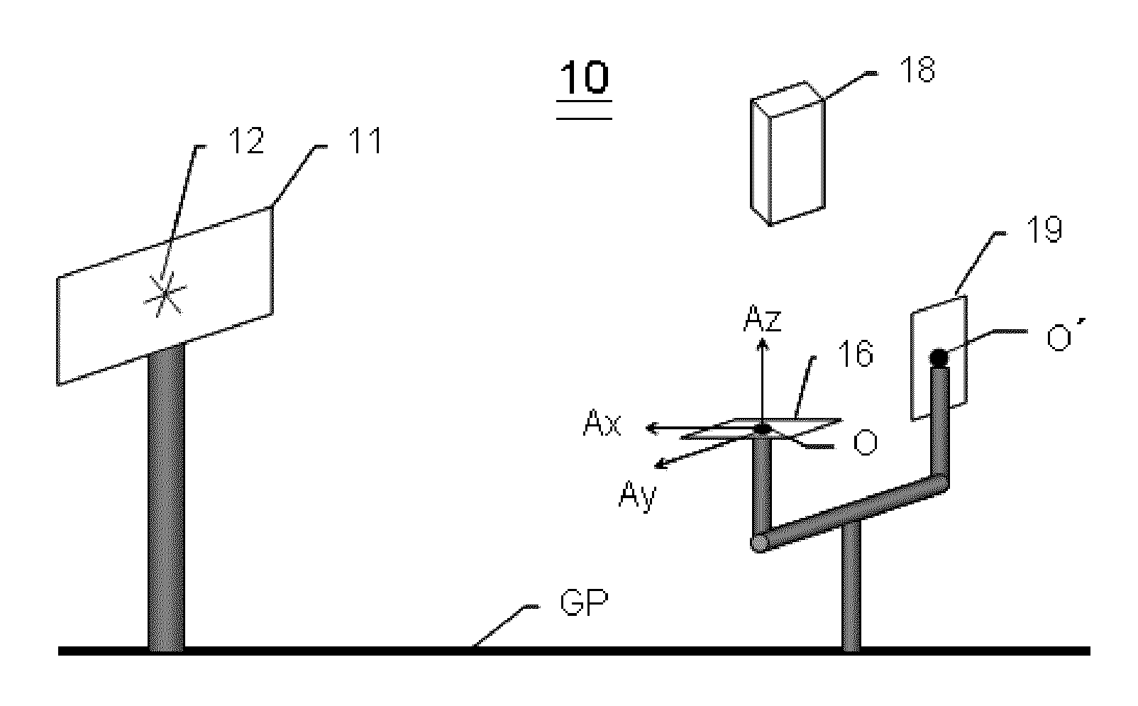
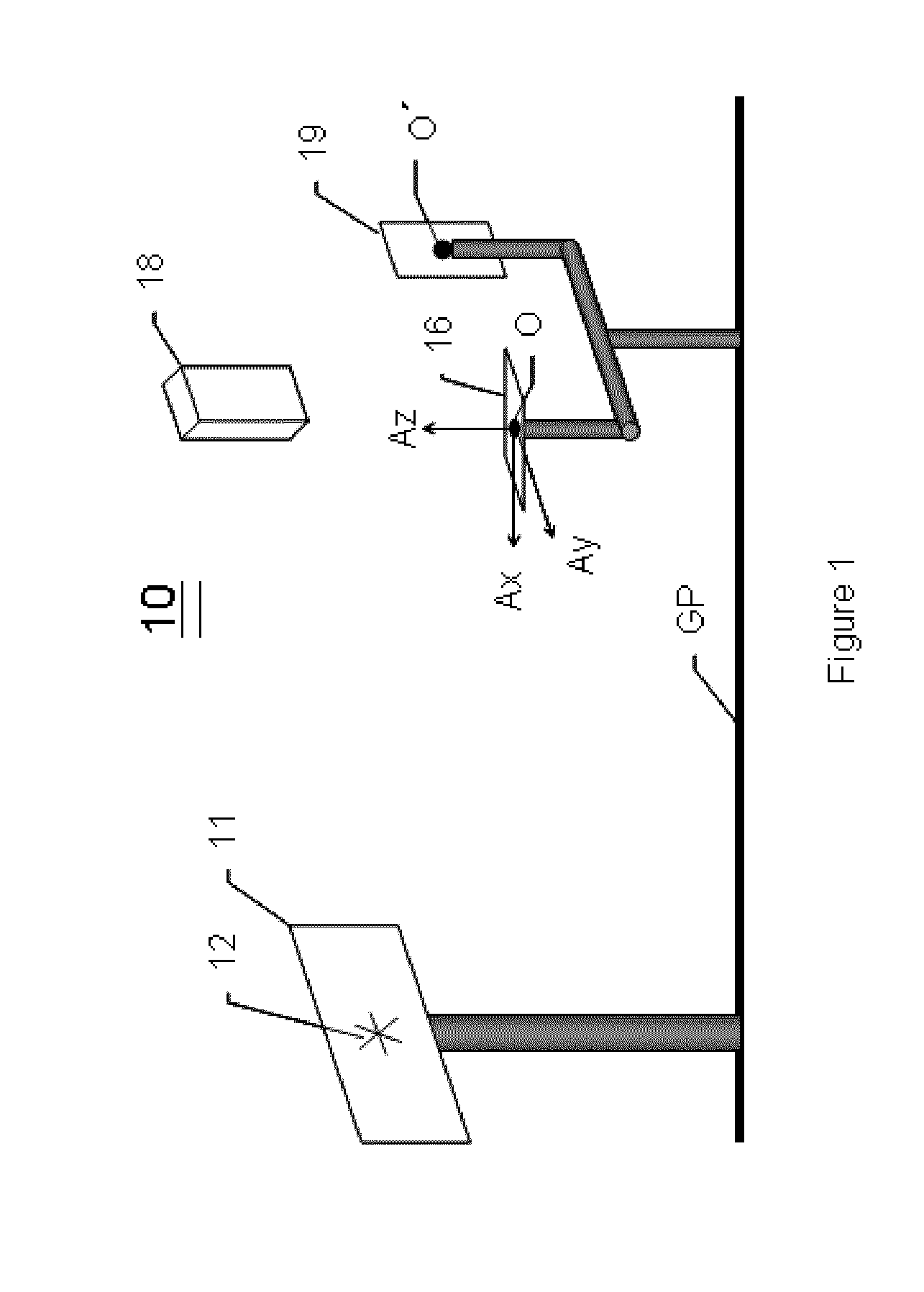
[0015]According to one series of embodiments, the invention is described in the context of a system and a method for locating a point in space based on receipt of a radio frequency (rf) signal from the point. In the illustrated example, all of the components are terrestrially based, but the invention is not limited to determination of location with respect to propagation between points over a ground plane. As used herein, the term point corresponds to a point in space or to a region associated with the location of an object wherein the location of the region could be approximately described by the point.

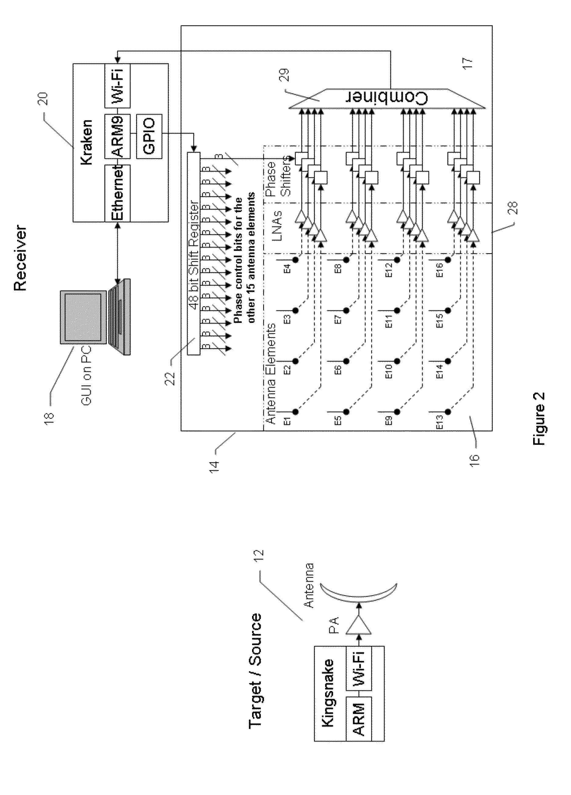
[0016]According to an embodiment of the invention, FIGS. 1 and 2 illustrate components of a system 10 for establishing the direction of location of an object 11 based on a radiating source 12 co-located with the object. The direction of location, i.e., a pointing direction, is determined relative to a position 13 which is the origin, O, of a reference coordinate system. Programmable ...


PUM


Abstract

A method for locating a point in a first region based on receipt of a rf signal from the point. An antenna array is in the first region at a first position rotatable about an axis. A series of phase-array patterns is provided for implementation with the antenna array to provide measures of rf signal strength. Each pattern provides a plurality of reference values as a function of angle. A plurality of the phase-array patterns are used to acquire, in the first region, a plurality of rf signal strength values based on reception of the rf signal. A set of correlation values is determined where each value is a correlation between signal strength reference values and rf signal strength values acquired based on reception of the rf signal from the point. The correlation values identify a direction relative to the first position along which the point is located.

Description

FIELD OF THE INVENTION[0001]The present invention relates to acquisition and characterization of position data useful for pointing in the direction of an object or determining the location of an object. More particularly, embodiments of the invention enable determination of the position of an object with improved effectiveness and reliability based on receipt of rf signals in a variety of environments. In one example, the system and method are applied to large terrestrial regions where the signal propagates over a ground plane.BACKGROUND OF THE INVENTION[0002]Many systems have been developed which require locating an object in a coordinate system or at least pointing to an object with high alignment precision. In many instances, when components of a system are to be aligned with respect to one another, the components are situated large distances, e.g., multiple miles, apart. In the past, the processes of pointing and locating have been subject to time consuming effort due to numerou...

Claims


Application Information

Patent Timeline
Patent Type & Authority Applications(United States)
IPC IPC(8): H01Q3/00G01S3/02
CPCH01Q3/04G01S3/44G01S3/023H01Q3/26
Inventor HARRIMAN, ADAM
Owner SAGRAD
Why Eureka
Try Eureka