Digital Rendering Method for Environmental Simulation

a digital rendering and simulation technology, applied in the field of video simulation production methods, can solve the problems of limited simulation realism, large load times, and existing rendering methods that require significant processing power to render a single, and achieve the effect of less processing power

Inactive Publication Date: 2013-01-17
2XL GAMES
View PDF19 Cites 24 Cited by
  • Summary
  • Abstract
  • Description
  • Claims
  • Application Information

AI Technical Summary

Benefits of technology

[0009]The simulated environment is created by rendering, in sequence, one or more particular sets to present the sporting event. The sequence of rendered sets represents progress through the simulated environment, such as by hitting consecutive golf shots to progress from tee to pin of a hole. Where multiple sets are present in the set database, an algorithm is used to select the proper set, then simulation elements are incorporated into the proper set before rendering the simulated camera's view to the display. The physics of movement within the simulation

Problems solved by technology

Unfortunately, existing rendering methods require significant processing power to render a single scene, which in a golf simulation may include the ground and sky, the green, the fairway, water and sand hazards, vegetation, background elements such as homes or spectators, the golfer's avatar, and the ball and associated physics, because each of these elements is represented by polygons.
As a result, the realism of the simulation is limited by the processing power of the system, and load times may be extensive.
This is particularly problematic for computing devices such as smartphones and tablet computers

Method used


Image

  • Digital Rendering Method for Environmental Simulation
  • Digital Rendering Method for Environmental Simulation
  • Digital Rendering Method for Environmental Simulation

Examples


first embodiment

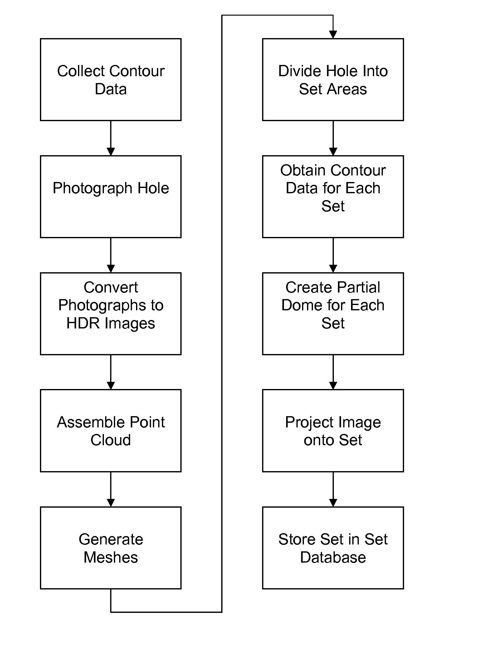
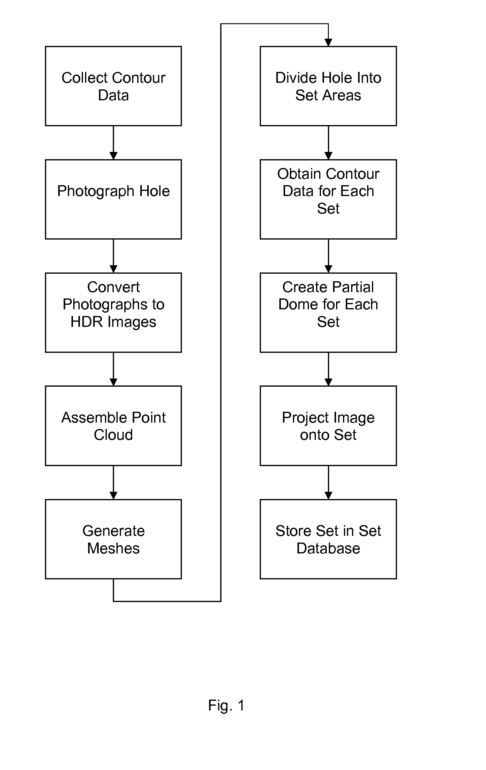
[0025]Referring to FIGS. 2-6, a set 11 is created for each collected image 12. In a first embodiment, the set 11 comprises a simulated camera 16 having a position and a heading, a backdrop 13, and one of the images 12 projected onto the backdrop 13. The virtual position and heading of the simulated camera are obtained from the geographical position and heading of the imaging device at the imaging device location where the image 12 was collected. Specifically, the imaging device's real-world or relative location and heading is transformed to a virtual position and heading in relation to the assembled contour data. The backdrop 13 comprises a mesh of polygons facing the simulated camera 16 and positioned a predetermined distance, with respect to the contour data, from the simulated camera 16. In one embodiment, the distance is determined by placing the center of the backdrop 13 at the intersection of the simulated camera's 16 heading and a predetermined hole 20 boundary (not shown). T...

second embodiment

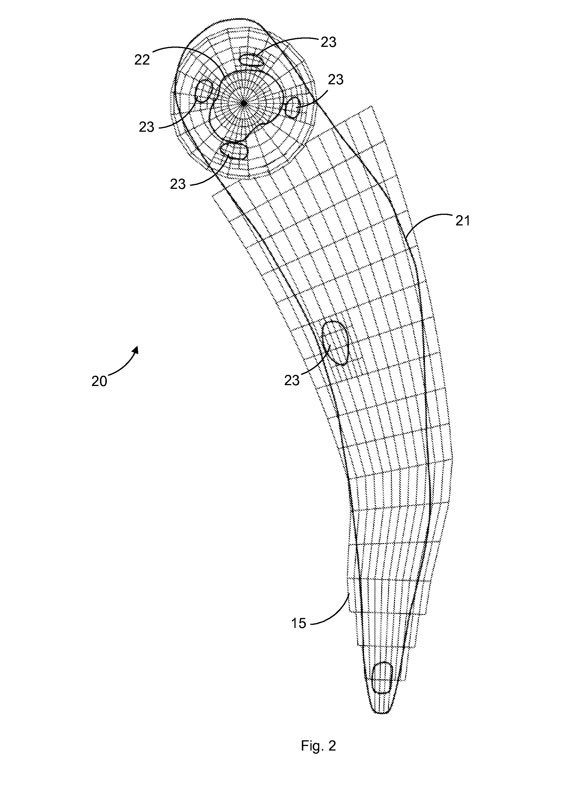
[0028]In a second embodiment, the set 11 further comprises the contour data, comprising meshes and geometric primitives 25, for a discrete area 15 of the hole 20. The area 15 to be represented is determined using the geographic position and heading of the camera when the image was captured. The hole 20 may be divided into areas 15 of equal size, but preferably the areas 15 are scaled according to the level of detail expected in the area 15. For example, areas 15 may be larger near the tee box and in the fairway, where significant amounts of terrain are traversed with a single shot, and smaller and more numerous in sand bunkers 23 and on the green 22, where there is greater variation of ball location and a higher level of detail is needed. Further, preferably the hole 20 is divided in a substantially gridlike manner except for the green 22, which is divided substantially radially as shown in FIG. 2. The radial division allows the simulated camera to always point towards the hole wher...


PUM


Abstract

A method for producing video simulations uses two-dimensional HDR images and LIDAR optical sensor data to deliver a photo-realistic simulated sporting event experience to a display. The playing environment is mapped using a data collection process that includes contour mapping the environment, photographing the environment, and associating the images with the contour mapping data. Preferably, the HDR camera is used in conjunction with a differential global positioning system that records the position and heading of the camera when the photo is taken. A polygon mesh is obtained from the contour data, and each image is projected onto a backdrop from the perspective of a simulated camera to create a set, which is then stored in a set database. The simulated environment is created by selecting the set needed for the simulation and incorporating simulation elements into the set before rendering the simulated camera's view to the display.

Description

CROSS-REFERENCE TO RELATED APPLICATIONS[0001]This application is a nonprovisional application and claims the benefit of copending U.S. Pat. App. Ser. No. 61 / 507,555, filed Jul. 13, 2011 and incorporated herein by reference.FIELD OF INVENTION[0002]This invention relates to methods of producing video simulations. This invention relates particularly to a method for producing sports simulations on a computer.BACKGROUND[0003]The use of computer-generated imagery (“CGI”) to create sports simulations is well known, dating back to the first video games released for arcade and console video game systems in the mid-1980s. In addition, television broadcast producers use CGI and digital rendering processes to illustrate aspects of the sport during a broadcasted event. Approaches to simulating a sporting event vary, but the most prevalent modern approach endeavors to create a course, arena, or field environment that is as true-to-life as possible. Such an environment includes the visual appearan...

Claims


Application Information

Patent Timeline
IPC IPC(8): G06T17/00G06T15/40G06T15/00
CPCG06T15/00G06T17/00A63F13/10A63F2300/66A63F2300/1093A63F2300/6009A63F13/12A63F13/525A63F13/812
Inventor RINARD, ROBBBALTMAN, RICK
Owner 2XL GAMES
Why Eureka
Try Eureka