Fiber optic distribution device

a fiber optic distribution and fiber optic technology, applied in the field of fiber optic distribution devices, can solve the problems of high installation cost, rigid housing, high installation cost, etc., and achieve the effect of reducing fire load, speeding up ftth deployment, and maintaining flexibility of cable routing

Inactive Publication Date: 2013-01-17
CCS TECH INC
View PDF9 Cites 23 Cited by
  • Summary
  • Abstract
  • Description
  • Claims
  • Application Information

AI Technical Summary

Benefits of technology

[0011]This invention allows cable termination points to reside inside existing duct architectures while still allowing the termination of cables in a standard way and maintaining flexibility of cable routing. The invention allows the termination of fibre optic cables in restricted spaces, avoiding floor termination boxes in public spaces. This helps to decrease fire load in each e.g. multi dwelling units. The advantage is that no stiff housing is used but a rather flexible housing, allowing the cable installation in given duct systems. This avoids problems during installation and therefore speeds up deployment of FTTH as well as lowers the fire load in publically used areas.

Problems solved by technology

Different kind of buildings like multi dwelling units and block of flats require complicated cabling systems which might mean that there are many separated cables, each one to connect one subscriber.
Installation of many cables which provide the connection between a main distribution point, which usually is located in the basement or in another place of the building, and the end user may cause many problems with routing through the wall or levels of the building.
As a result, such installations consume a lot of time and costs.
The installation of an optical cable comprising a riser cable and branched off tether cables to provide connection between the main distribution point and the subscribers is done by a highly skilled field technician using standard fiber optic distribution devices which results in high costs of installation.
Such fiber optic distribution device known from the prior art comprise housings being rigid and bulky.

Method used


Image

  • Fiber optic distribution device
  • Fiber optic distribution device
  • Fiber optic distribution device

Examples


Embodiment Construction

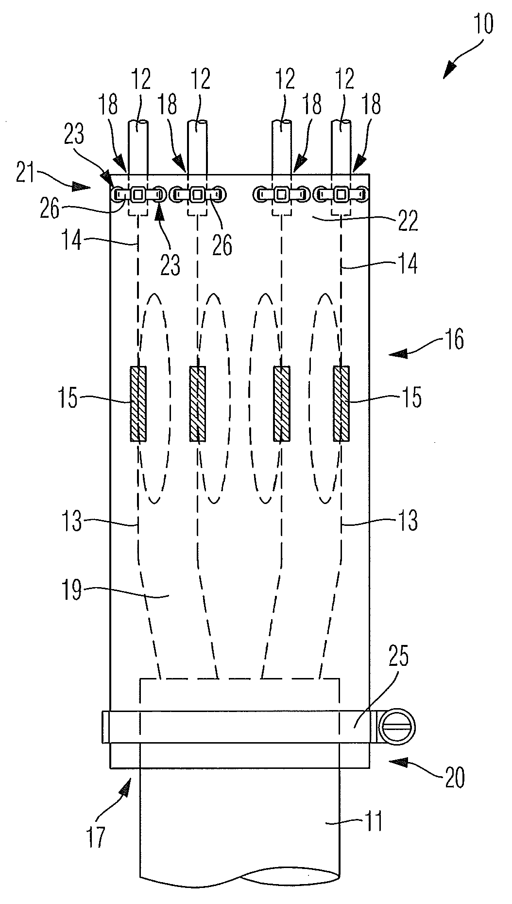
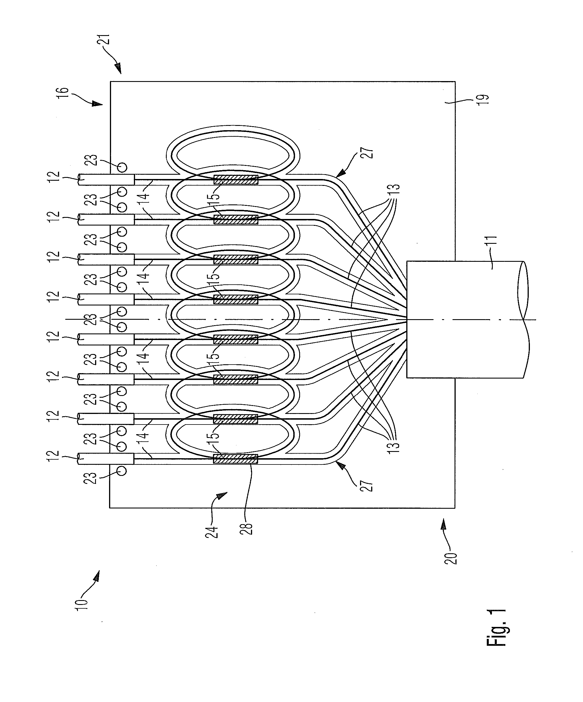
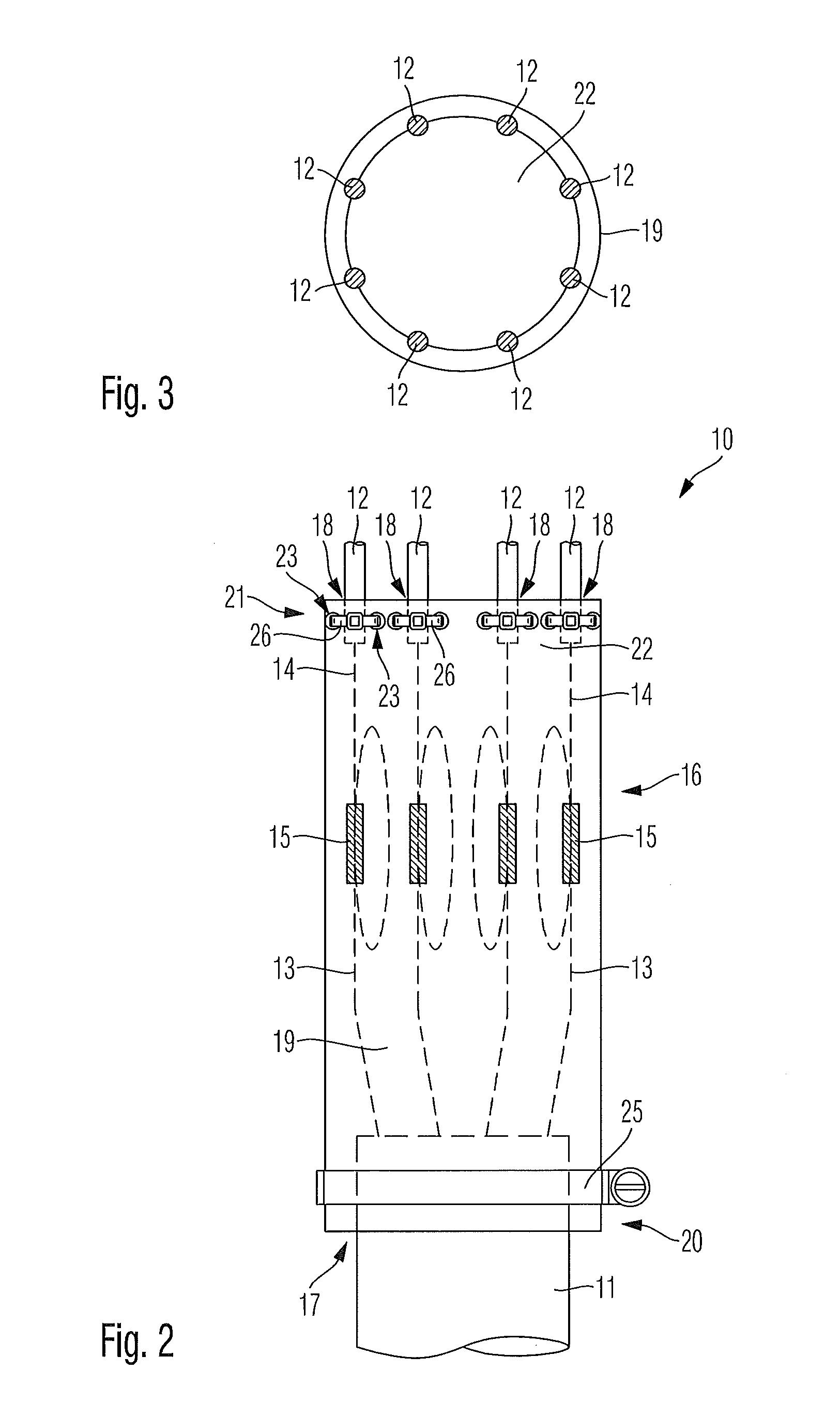
[0015]FIGS. 1, 2 and 3 show a preferred embodiment of a fiber optic distribution device 10 for indoor applications in combination with a single first fiber optic cable 11 and a plurality of second fiber optic cables 12.

[0016]The shown first fiber optic cable 11 can be a riser cable or alternatively a tether cable having a plurality of optical fibers 13. The shown second fiber optic cables 12 can be tether cables or alternatively drop cables each having at least one, in the shown embodiment a single one, optical fiber 14 branched off the or each first fiber optic cable 11.

[0017]The optical fibers 14 of the second fiber optic cables 12 are connected with the optical fibers 13 of the first fiber optic cable 11 by splices or connectors. The embodiment shows splices 15 between the same.

[0018]The connection points or splices 15 between the optical fibers 13, 14 are handled in said fiber optic distribution device 10.

[0019]The fiber optic distribution device 10 comprises a housing 16. Said ...


PUM


Abstract

A fiber optic distribution device for indoor applications is disclosed. The fiber optic distribution device comprises a housing having at least one inlet opening for at least one first fiber optic cable having a plurality of optical fibers and a plurality of outlet openings for a plurality of second fiber optic cables each having at least one optical fiber branched off the or each first fiber optic cable. The housing comprises a flexible housing part being transferable between an open status having a flat shape and a closed status having a bent shape being partially wound around the first fiber optic cable.

Description

RELATED APPLICATIONS[0001]This application claims the benefit of priority under 35 U.S.C. §119 of European Patent Application Serial No. 11167711.8 filed May 26, 2011 the content of which is relied upon and incorporated herein by reference in its entirety.BACKGROUND[0002]1. Field of the Disclosure[0003]The patent application relates to a fiber optic distribution device for indoor applications, especially to a floor box. Further on, the patent application relates to an assembly comprising such a fiber optic distribution device and fiber optic cables.[0004]2. Technical Background[0005]In the world of the ever-increasing need for broadband bandwidth optical cables have become the main part of telecommunication networks. Optical cables can transmit voice signals, data signals and video signals for very long distances with very high speed. Developments of optical telecommunication networks allow the connection of the end user directly to the optical fiber. This kind of network technology...

Claims


Application Information

Patent Timeline
Patent Type & Authority Applications(United States)
IPC IPC(8): G02B6/46
CPCG02B6/4471
Inventor KNUTH, THOMAS
Owner CCS TECH INC
Why Eureka
Try Eureka