
Image forming apparatus and method of driving the same

a technology of image forming apparatus and drive motor, which is applied in the direction of electric motor speed/torque regulation, instruments, control systems, etc., can solve the problems of increased cost and noise, and difficulty in ensuring a proper torque margin in the driving motor

Active Publication Date: 2013-01-17
HEWLETT PACKARD DEV CO LP
View PDF6 Cites 10 Cited by
  • Summary
  • Abstract
  • Description
  • Claims
  • Application Information

AI Technical Summary

Benefits of technology

The patent text describes an image forming apparatus that can safely operate under low temperatures and high driving loads. It includes an image forming unit, a driving motor, an environment recognizing unit, and a controller. The controller controls the image forming unit and the driving motor to decrease the driving load of the image forming unit and to perform a warm-up operation by driving the driving motor under normal warm-up driving conditions. The technical effect of this invention is to improve the performance and reliability of image forming apparatuses in low temperature environments with high driving loads.

Problems solved by technology

Increasing only torque increases cost and noise, and the driving motor may have a proper torque margin at a normal temperature and under normal conditions.
However, it is difficult to secure a proper torque margin since a load is increased at a low temperature.
If a torque margin is inappropriate, a defect may be generated in the driving motor.
However, in such method, it is difficult to predict a time to drive the driving motor such that a time to drive a photoreceptor of the developing unit may be extended, thereby affecting a lifespan of the developing unit.
Also, if a torque margin is not secured due to environmental factors, printing may not be performed due to a recording medium being jammed or the driving motor being stalled.
In exemplary embodiments, the controller may generate a driving error signal if a number of the re-drivings reaches a maximum number of re-driving operations.

Method used


Image

  • Image forming apparatus and method of driving the same
  • Image forming apparatus and method of driving the same
  • Image forming apparatus and method of driving the same

Examples


Embodiment Construction

[0033]Reference will now be made in detail to exemplary embodiments of the present general inventive concept, examples of which are illustrated in the accompanying drawings, wherein like reference numerals refer to the like elements throughout. Exemplary embodiments are described below in order to explain the present general inventive concept while referring to the figures.

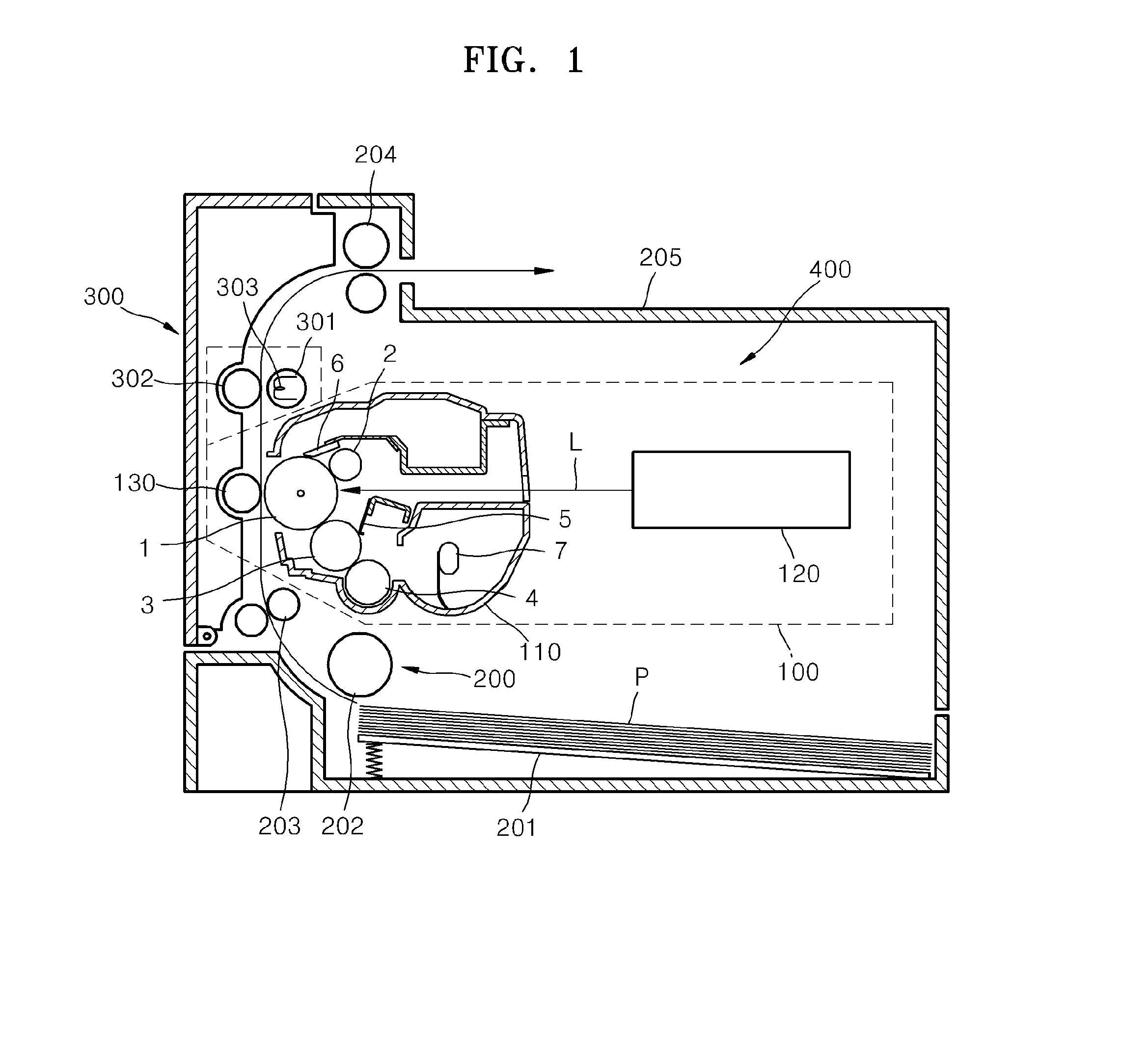
[0034]FIG. 1 is a view illustrating an electrophotographic image forming apparatus according to exemplary embodiments of the present general inventive concept. The image forming apparatus may be a monochromatic electrophotographic image forming apparatus employing a dry mono-component toner. Referring to FIG. 1, an image forming unit 400 to form an image on a recording medium P includes a developing unit 100, a paper feeding unit 200, and a fixing unit 300.

[0035]The paper feeding unit 200 picks up the recording medium P on which an image is to be printed from a paper feeding cassette 201 and discharges the recordi...


PUM


Abstract

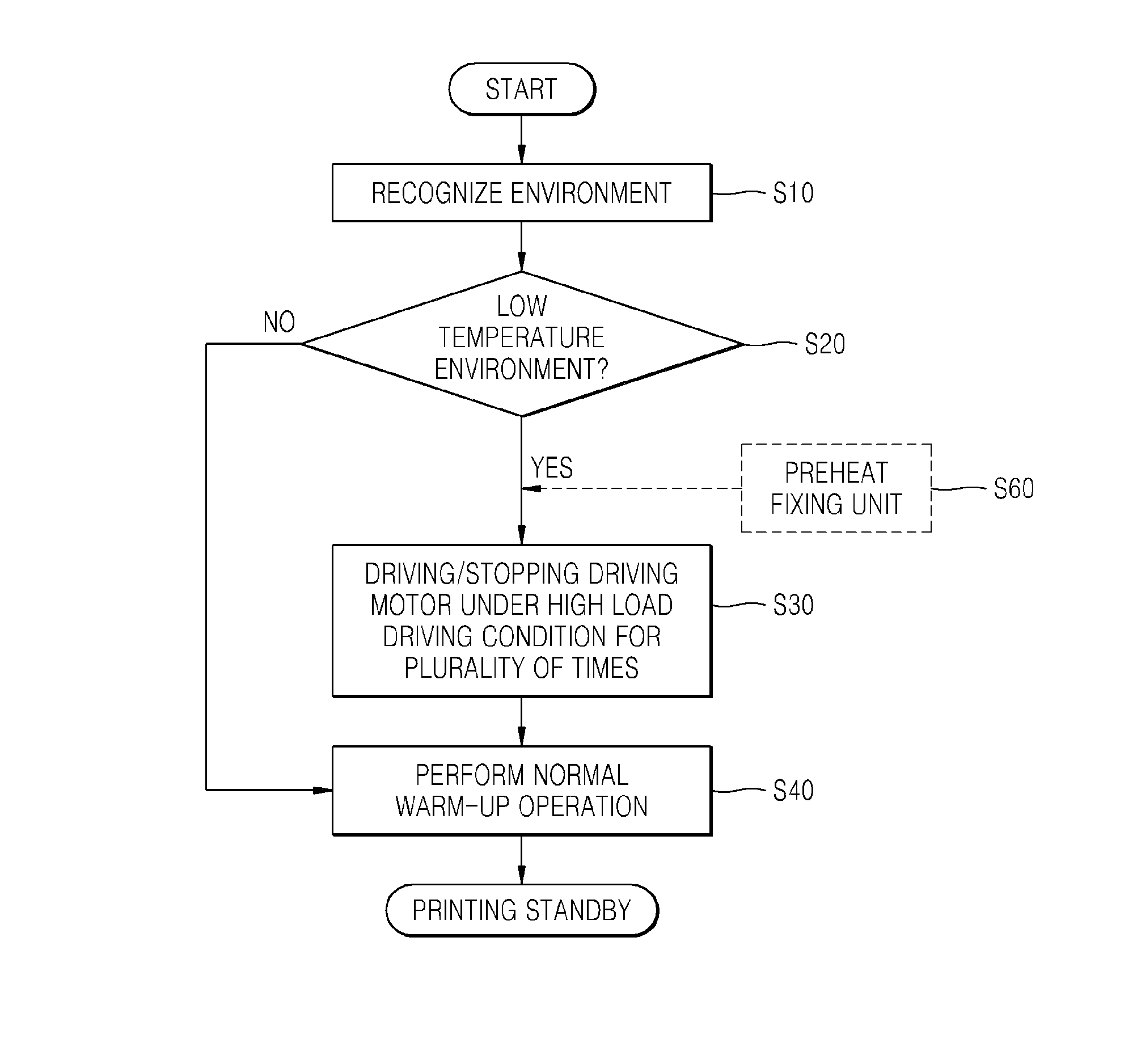
An image forming apparatus and a method of driving the same are provided in which, if a driving environment is determined to be a low temperature environment, a driving load of an image forming unit is decreased by repeating driving and stopping a driving motor under a high load driving condition to generate a torque higher than a torque generated under a normal warm-up driving condition; and a warm-up operation is performed by driving the driving motor under the normal warm-up driving condition.

Description

CROSS-REFERENCE TO RELATED APPLICATIONS[0001]This application claims priority from and the benefit under 35 U.S.C. §119 to Korean Patent Application No. 10-2011-0068979, filed on Jul. 12, 2011, in the Korean Intellectual Property Office (KIPO), the disclosure of which is incorporated herein in its entirety by reference.BACKGROUND[0002]1. Field[0003]The present general inventive concept relates to an image forming apparatus including a driving motor and a method of driving the image forming apparatus.[0004]2. Discussion of the Background[0005]In electrophotographic image forming apparatuses, light representing image information is radiated to a photoconductor to form an electrostatic latent image on a surface of the photoconductor, toner is supplied to the electrostatic latent image to develop the electrostatic latent image into a visible toner image, and then the visible toner image is transferred and fixed on a recording medium, thereby printing an image on the recording medium.[00...

Claims


Application Information

Patent Timeline
Patent Type & Authority Applications(United States)
IPC IPC(8): G03G15/00G03G15/20
CPCG03G15/5008G03G2215/00556G03G15/6529G03G15/14H02P5/00
Inventor KIM, YUN-SUSHIN, DAE-LIMCHOI, HONG-CHUL
Owner HEWLETT PACKARD DEV CO LP
Learn More