Method of Shifting a Tandem Drive Axle Having an Inter-Axle Differential

a technology of tandem drive axle and differential, which is applied in the direction of mechanical equipment, transportation and packaging, and vehicle drive train components, can solve the problems of increasing the cost and weight of inter-axle differential, reducing the fuel efficiency of the vehicle, and incorporating additional drive train components at added expense and weight, etc., so as to facilitate improved shifting, reduce windage and frictional losses, and reduce the cost and weight of the tandem drive axle.

Active Publication Date: 2013-01-17
DANA HEAVY VEHICLE SYSTEMS GROUP LLC
View PDF5 Cites 30 Cited by
  • Summary
  • Abstract
  • Description
  • Claims
  • Application Information

AI Technical Summary

Benefits of technology

[0007]Presently provided by the invention, a method of shifting a tandem drive axle system from a low speed and high torque tandem axle manner of operation to a high speed and low torque single axle manner of operation that reduces windage and frictional losses and facilitates improved shifting from one operating state to another without excessively increasing a cost and a weight of the tandem drive axle, has surprisingly been discovered.

Problems solved by technology

However, such versatility typically requires the incorporation of additional drive train components into the vehicle at added expense and weight.
Such added weight results in a decreased fuel efficiency of the vehicle.
However, incorporation of both the two-speed configuration, an axle disconnect function, and the inter axle differential may be prohibitive with respect to cost and weight.
Such added weight, windage losses, and frictional losses result in a decreased fuel efficiency of the vehicle.
Additionally, when components are provided to permit the disengagement of one of the driven axles or to transition from the vehicle from single axle operation to tandem axle operation, a complexity of the tandem drive axle is increased.
Typically, such operations may require manual engagement by an operator when specific conditions are present or may require the operator to stop the vehicle to engage specific components.
Such features, while providing additional functionality to the vehicle, may not be properly implemented by the operator or may not be used at all by the operator.
When such features are not properly implemented, a shift from one operating state to another may result in damage to the tandem drive axle or a rough shift, either of which typically result in a dissatisfaction of the operator.

Method used


Image

  • Method of Shifting a Tandem Drive Axle Having an Inter-Axle Differential
  • Method of Shifting a Tandem Drive Axle Having an Inter-Axle Differential
  • Method of Shifting a Tandem Drive Axle Having an Inter-Axle Differential

Examples


Embodiment Construction

[0017]It is to be understood that the invention may assume various alternative orientations and step sequences, except where expressly specified to the contrary. It is also to be understood that the specific devices and processes illustrated in the attached drawings, and described in the following specification are simply exemplary embodiments of the inventive concepts defined in the appended claims. Hence, specific dimensions, directions or other physical characteristics relating to the embodiments disclosed are not to be considered as limiting, unless the claims expressly state otherwise.

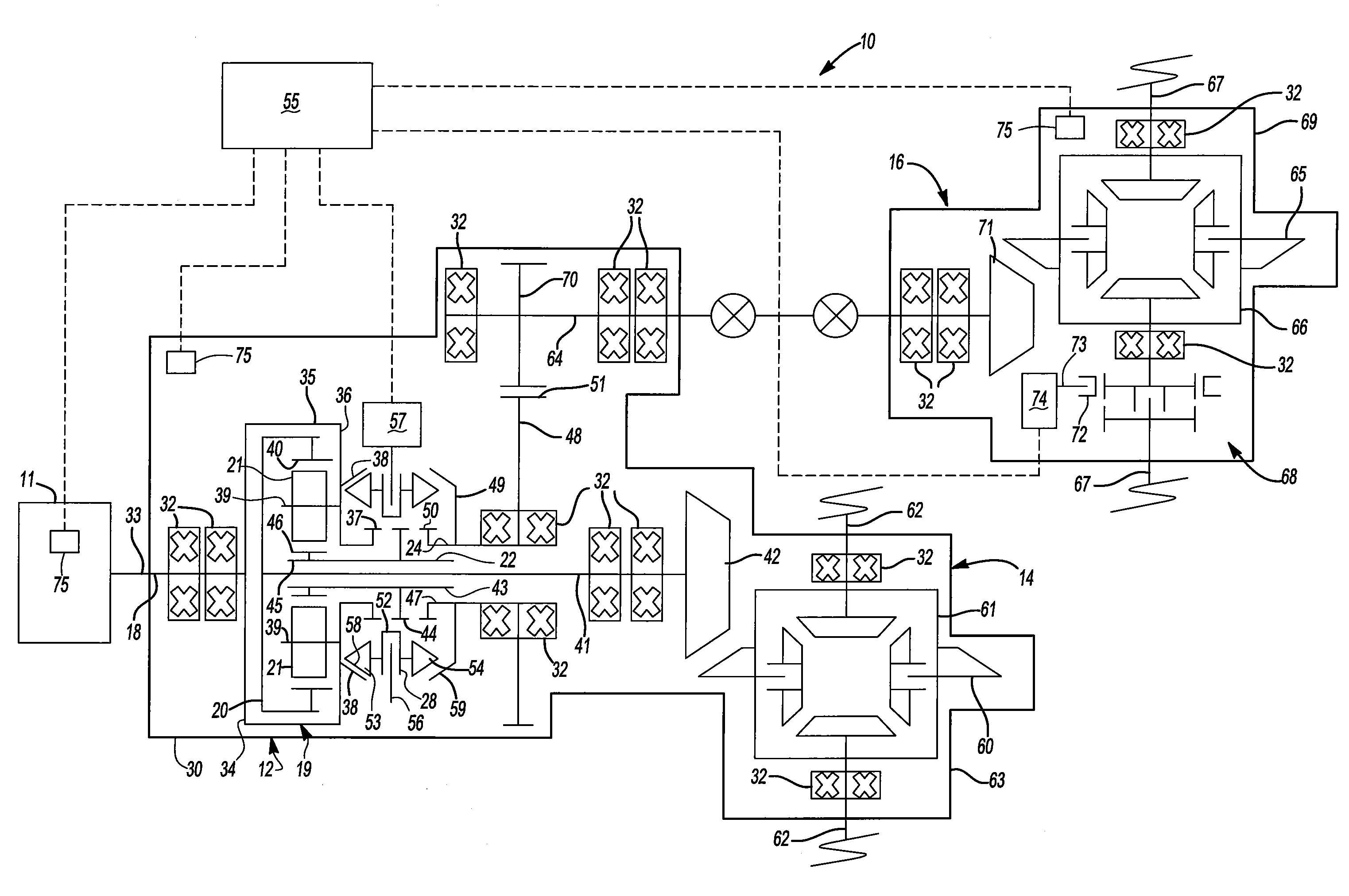
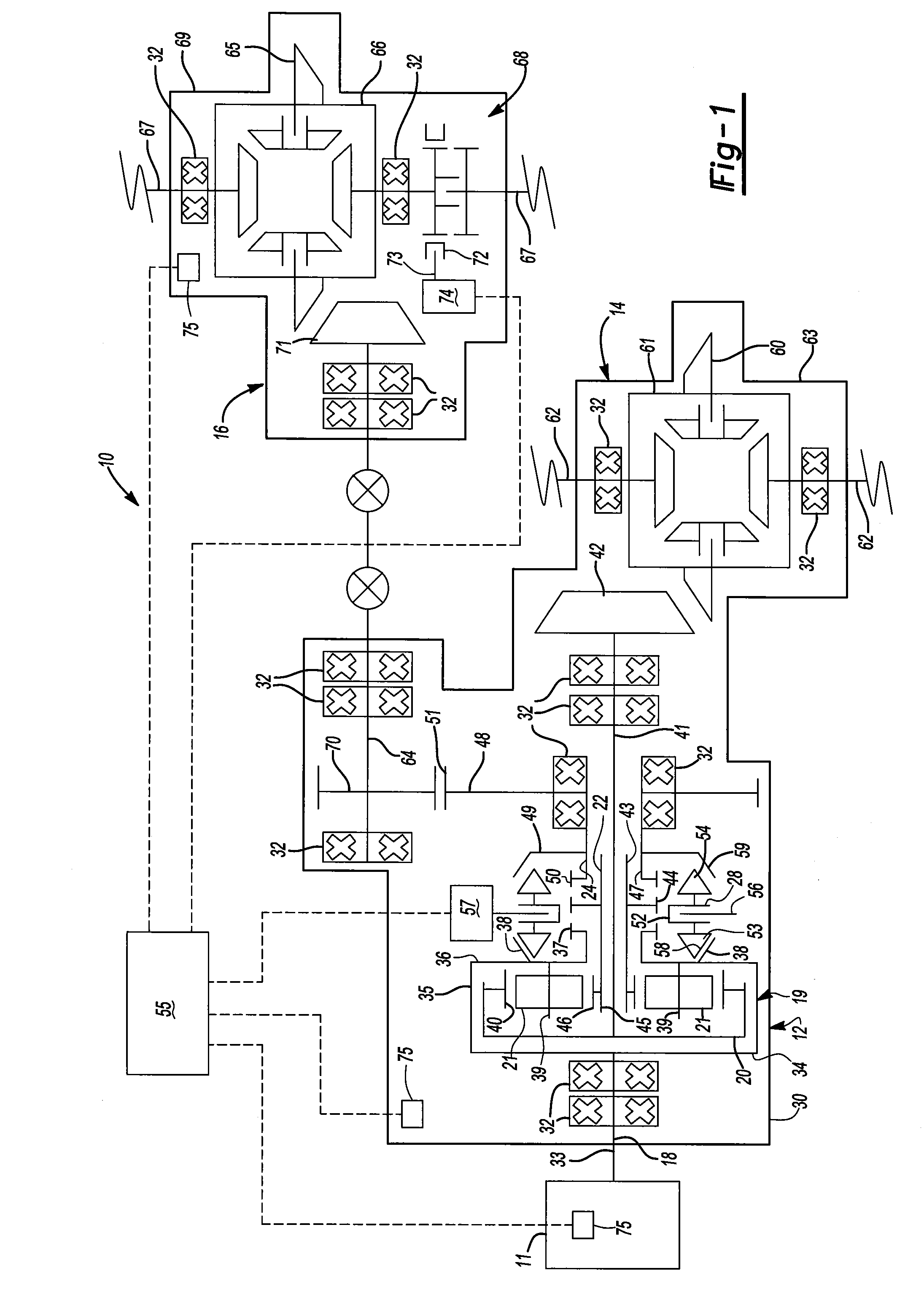
[0018]FIG. 1 illustrates a drive axle system 10 for a vehicle having a power source 11. The drive axle system 10 preferably includes a power distribution unit 12, a first axle assembly 14, and a second axle assembly 16. The drive axle system 10 is drivingly engaged with a power source 11. As shown, the drive axle system 10 includes the three assemblies 12, 14, 16, but it is understood the drive ax...


PUM


Abstract

A method of shifting a power distribution unit for a vehicle from a first operating state to a second operating state is provided. The method includes the step of adjusting a rotational speed of a portion of a second axle assembly using a clutching device to impart energy to a lubricant within the second axle assembly. A controller in communication with a power source of the vehicle adjusts an operating condition of the power source to facilitate moving the clutching device. The power distribution unit includes an inter-axle differential capable being placed in a locked condition by the clutching device and of accommodating a rotational difference between a first output gear and a second output gear with the inter-axle differential.

Description

CLAIM OF PRIORITY[0001]The present application claims priority to and incorporates by reference U.S. Provisional Application No. 61 / 435,007 filed Jan. 21, 2011, entitled “Two Speed Tandem Drive Axle Having an Inter-Axle Differential.”FIELD OF THE INVENTION[0002]The present invention relates to a vehicle drive train and to a method of shifting a tandem drive axle for the vehicle drive train having an inter-axle differential from a first operating state to a second operating state.BACKGROUND OF THE INVENTION[0003]Vehicles incorporating tandem drive axles benefit in many ways over vehicles having a single driven axle. Inter-axle differentials in such vehicles may be configured to distribute torque proportionately or disproportionately between the axles. Additionally, shift mechanisms may be provided to such vehicles to permit the disengagement of one of the driven axles or to transition from single axle operation to tandem axle operation, among other benefits. However, such versatility...

Claims


Application Information

Patent Timeline
Patent Type & Authority Applications(United States)
IPC IPC(8): B60W10/16
CPCY10T477/679Y10T477/6403B60K17/16Y10T477/613Y10T477/606
Inventor MORSCHECK, TIMOTHY J.COOPER, KENNETH E.ZIECH, JAMES F.NELLUMS, RICHARD A.WESOLOWSKI, STEVEN J.REMBOSKI, DONALD J.
Owner DANA HEAVY VEHICLE SYSTEMS GROUP LLC
Why Eureka
Try Eureka