Surgical instrument for the positioning of an alignment element

a surgical instrument and alignment element technology, applied in the direction of shoulder joints, prostheses, osteosynthesis devices, etc., can solve the problems of fracture or perforation, inconvenient operation, and inability to accurately position the indicator pin, so as to achieve fast and accurate positioning and efficient removal

Active Publication Date: 2013-01-17
MATERIALISE NV
View PDF9 Cites 55 Cited by
  • Summary
  • Abstract
  • Description
  • Claims
  • Application Information

AI Technical Summary

Benefits of technology

[0028]The surgical fixtures according to the present invention allow for a fast and accurate positioning of an indicator pin, wire, screw or drill, and allow for an efficient removal of the fixture from the anatomy after use.

Problems solved by technology

However, this procedure is technically more difficult and time-consuming than the primary intervention and the outcome is often less satisfactory, both because there is less bone stock to work with and because the removal of adherent cement or prosthetic components may result in fracture or perforation of the bone.
Furthermore, with each successive joint revision, the risk of infection and symptomatic loosening of the prosthesis may increase substantially.
In addition, the transverse ligament is generally obscured from the surgeon's view, further hampering the orientation process.
Furthermore, the impactor and hammer are both rather bulky, making it difficult to keep the impactor in a stable orientation.
Few practical solutions have been proposed for these problems.
However, it is very doubtful whether such a device could be able to withstand the momentum applied to it during impaction.

Method used


Image

  • Surgical instrument for the positioning of an alignment element
  • Surgical instrument for the positioning of an alignment element
  • Surgical instrument for the positioning of an alignment element

Examples


example 1

Surgical Fixture with Multiple Contact Elements

[0103]The surgical fixtures according to the present invention may comprise more than one contact element. FIG. 3 shows such a surgical fixture (1) according to a particular embodiment of the present invention. The fixture comprises a positioning element (3) and four contact elements (2, 2′), each comprising a patient-specific contact surface (4). The positioning element forms a single unit with one of the contact elements (2′), and comprises a hole (5) for insertion of an alignment element and holes (6) for insertion of fixation elements. The hole (5) for insertion of an alignment element may also be used for drilling a hole in the pelvic bone. Thus, the positioning element is also a drill guide (9), more particularly a drilling cylinder. Each of the contact elements (2, 2′) extends from a connecting structure (12). The connection (11) between the positioning element (3) and the connecting structure (12) is adapted, such that the posit...

example 2

Surgical Fixture with One Contact Element

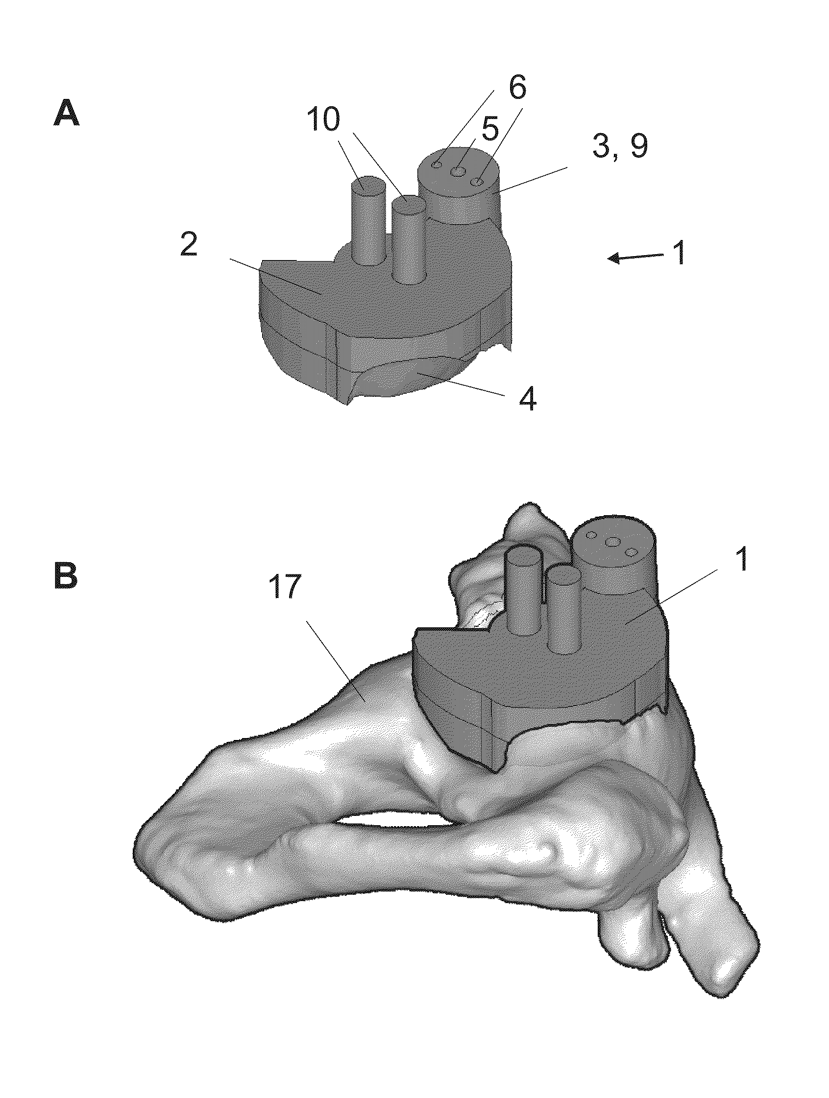
[0104]The surgical fixtures according to the present invention may comprise only one contact element. FIG. 4 A shows such a surgical fixture (1) according to a particular embodiment of the present invention. The fixture comprises a positioning element (3) and one contact element (2). The contact element comprises a patient-specific contact surface (4). The positioning element is attached to the contact element (2), and comprises a hole (5) for insertion of an alignment element and holes (6) for insertion of fixation elements. The hole (5) for insertion of an alignment element may also be used for drilling a hole in the pelvic bone. Thus, the positioning element is also a drill guide (9), more particularly a drilling cylinder. The connection between the positioning element (3) and the contact element (2) is adapted (not shown), such that the positioning element can be easily detached from the surgical fixture with surgical cutting instruments....


PUM

PropertyMeasurementUnit
angleaaaaaaaaaa
angleaaaaaaaaaa
angleaaaaaaaaaa

Abstract

The present invention relates to surgical instruments and methods for the manufacture thereof, for facilitating the positioning of an implant in a socket of a ball-and-socket joint, by positioning an alignment element such as a pin, wire, screw or drill.

Description

FIELD OF THE INVENTION[0001]The present invention relates to surgical instruments for positioning an alignment element based on pre-operational planning, as well as to methods for the manufacture thereof.BACKGROUND[0002]In most joint arthroplasty, replacement and / or reconstruction surgery procedures, and in particular in hip and shoulder joint surgery, a joint is replaced by a prosthetic implant. The main goal of such interventions is to relieve (arthritic) pain and / or to restore severe physical joint damage. When prosthesis fails, a revision surgery is carried out. However, this procedure is technically more difficult and time-consuming than the primary intervention and the outcome is often less satisfactory, both because there is less bone stock to work with and because the removal of adherent cement or prosthetic components may result in fracture or perforation of the bone. Furthermore, with each successive joint revision, the risk of infection and symptomatic loosening of the pr...

Claims


Application Information

Patent Timeline
Patent Type & Authority Applications(United States)
IPC IPC(8): A61F2/46B23P17/04
CPCY10T29/49B23P17/04A61F2/46A61F2/4609A61B17/1739A61B17/1746A61B90/11A61B2017/00526A61B2017/568A61B2034/108A61F2/30942A61F2/4612A61F2/4657A61F2002/4677A61F2002/4687B33Y80/00
Inventor HANANOUCHI, TAKEHITOVANGENEUGDEN, DIETER
Owner MATERIALISE NV
Why Eureka
Try Eureka