Power transmission device and waveform monitor circuit for use in power transmission device

Active Publication Date: 2013-01-24
KONINKLJIJKE PHILIPS NV
View PDF9 Cites 21 Cited by
  • Summary
  • Abstract
  • Description
  • Claims
  • Application Information

AI Technical Summary

Benefits of technology

The present invention relates to a technology for preventing a negative voltage (lower than ground electric potential) from being input to a waveform detection circuit. The technical effect of this invention is to always set the electric potential of the waveform monitor signal higher than the ground electric potential, which prevents the negative voltage from being input to the waveform detection circuit. This improves the accuracy and reliability of waveform monitoring during power reception.

Problems solved by technology

Therefore, there exists a problem that the negative voltage is applied to the IC terminal of the power-transmission control device 420, thereby producing, for example, a parasitic effect (latch up, etc.) which causes breakdown of an electric circuit element included in the power-transmission control device 420.

Method used


Image

  • Power transmission device and waveform monitor circuit for use in power transmission device
  • Power transmission device and waveform monitor circuit for use in power transmission device
  • Power transmission device and waveform monitor circuit for use in power transmission device

Examples


embodiment 1

[0036][Schematic Configuration of Power Transmission System]

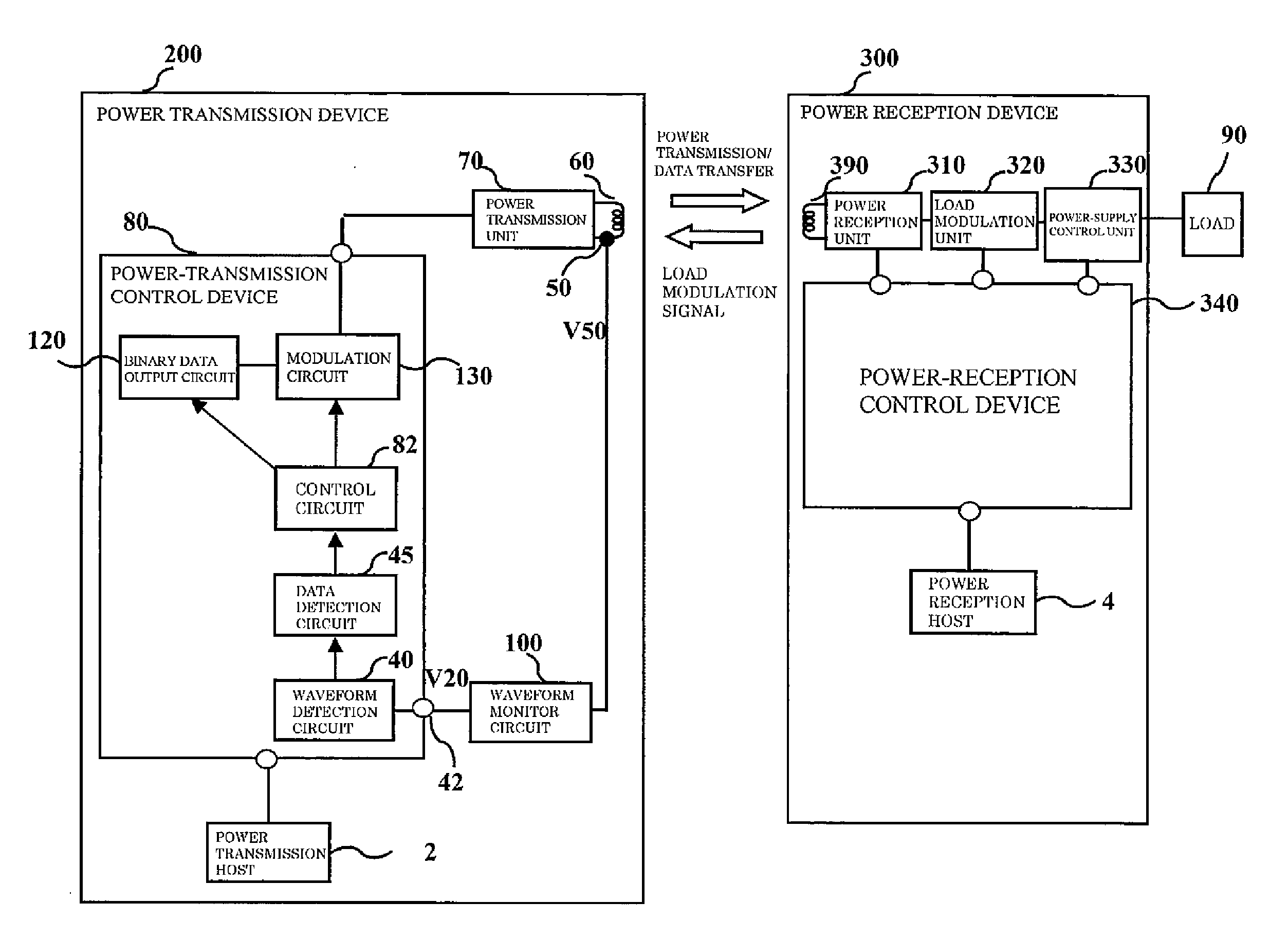
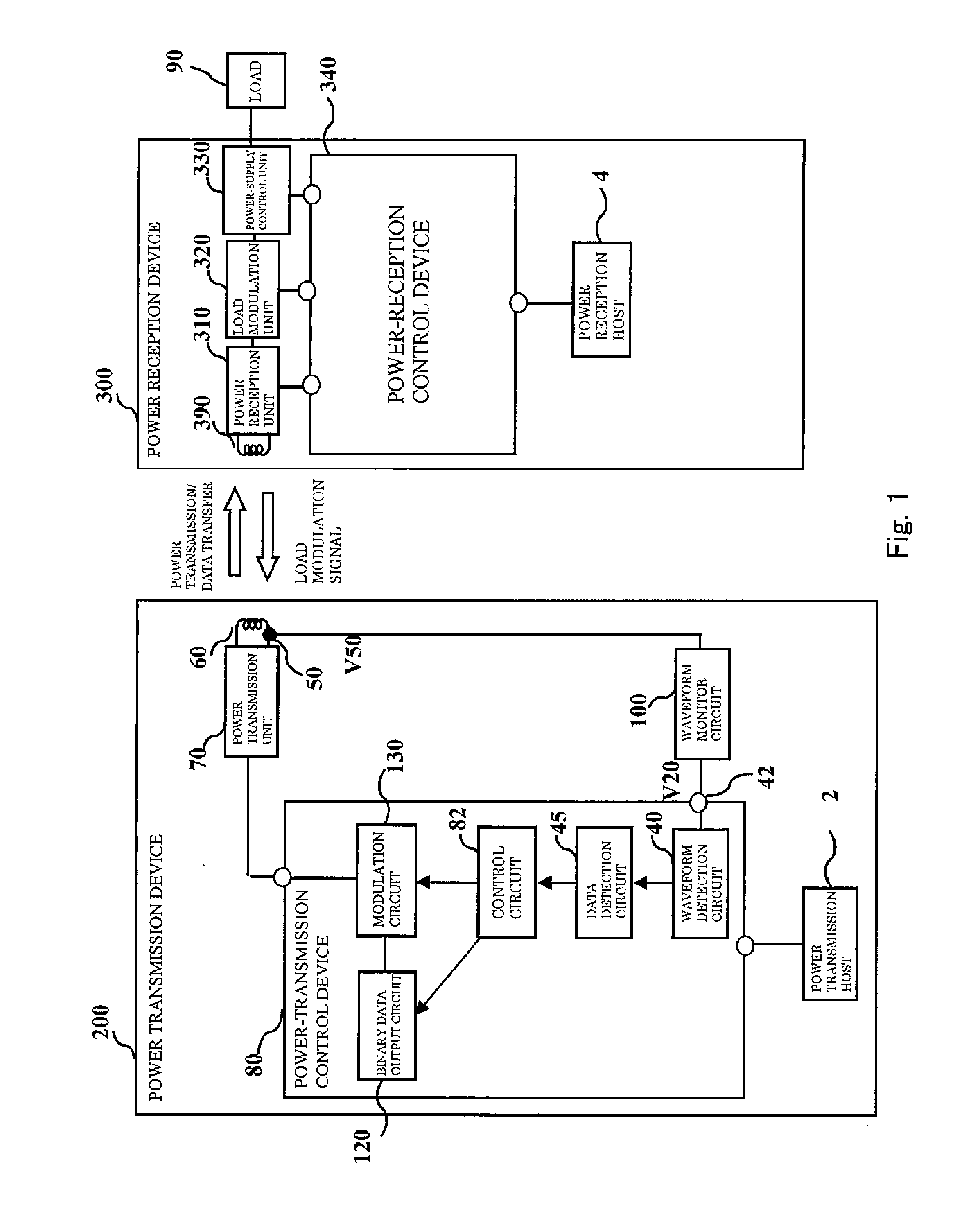
[0037]FIG. 1 is a block diagram showing the configuration of a power transmission system according to Embodiment 1 of the present invention.

[0038]Referring to FIG. 1, the power transmission system includes a power transmission device 200 including a primary coil 60 and a power reception device 300 including a secondary coil 390, and is configured such that the primary coil 60 and the secondary coil 390 are electromagnetically coupled together to construct a power transmission transformer. This enables electric power to be transmitted from the power transmission device 200 to the power reception device 300, and hence the electric power to be supplied to a load 90.

[0039]The power transmission device 200 is built into an apparatus at a power transmission side. The apparatus at the power transmission side is, for example, a charging apparatus. The power reception device 300 is built into electronic equipment at a power receptio...

embodiment 2

[0079][Configuration of Power Transmission System]

[0080]The configuration of a power transmission system of Embodiment 2 of the present invention is identical to that of Embodiment 1 of FIG. 1, and will not be described in detail.

[0081][Configuration of Waveform Monitor Circuit]

[0082]FIG. 6 is a circuit diagram showing the configuration of the waveform monitor circuit 100 according to Embodiment 2 of the present invention.

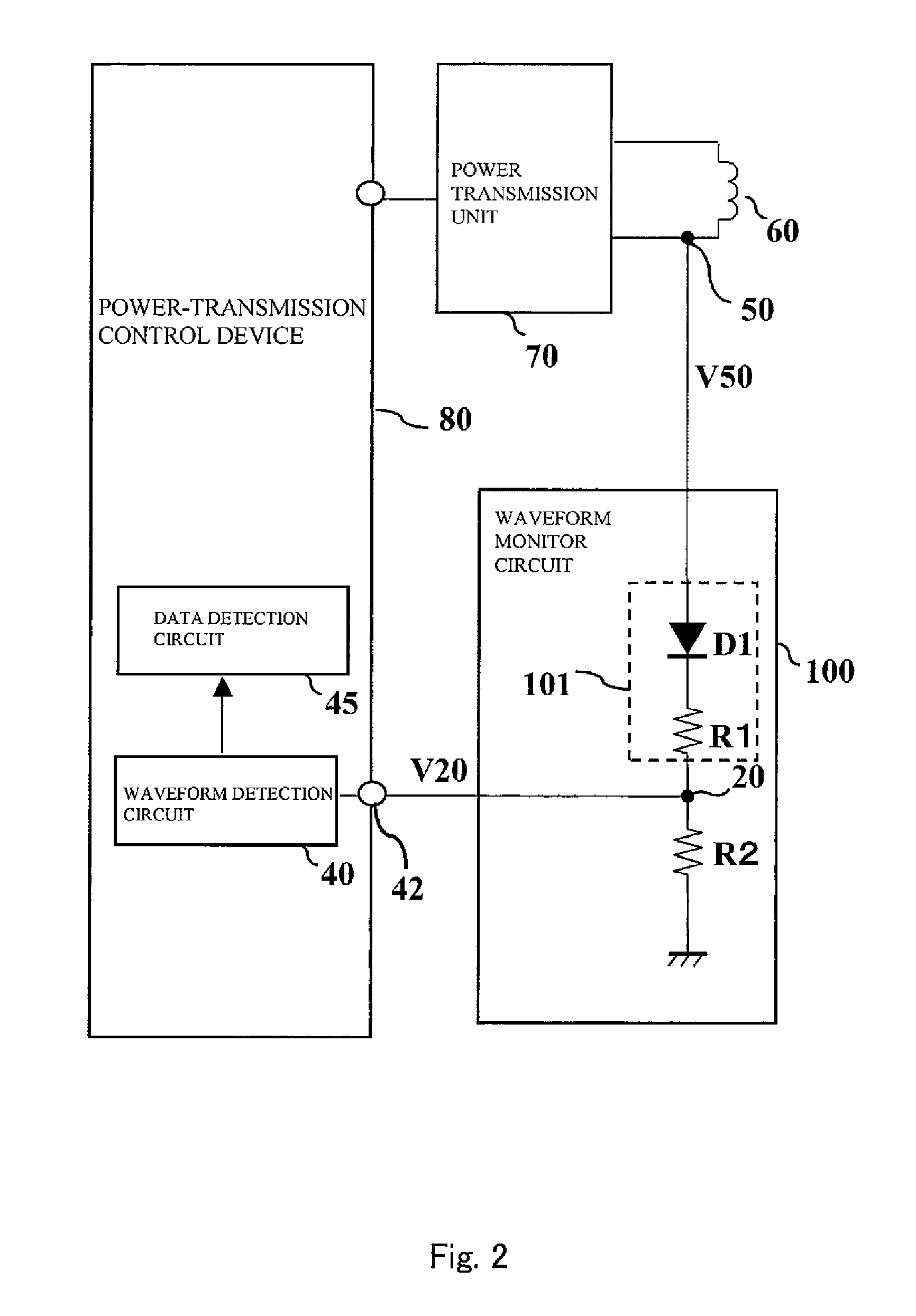
[0083]The waveform monitor circuit 100 of FIG. 6 is different from the waveform monitor circuit 100 of FIG. 2 in the position of the diode D1 and addition of a resistor R3 (third resistor) of the present invention).

[0084]The waveform monitor circuit 100 of FIG. 6 is configured in such a manner that the resistor R1 (second resistor of the present invention) and the resistor R2 (first resistor of the present invention) are connected in series between the coil end node 50 of the primary coil 60 and the ground terminal (low electric potential power supply node). A conn...


PUM


Abstract

A power transmission device in a power transmission system including the power transmission device including a primary coil and a power reception device including a secondary coil, the primary coil being electromagnetically coupled to the secondary coil, to receive in the power reception device AC power transmitted from the power transmission device, comprises a waveform monitor circuit configured to detect an electric potential at one end of the primary coil and output a waveform monitor signal formed by restricting the detected electric potential to an electric potential which is equal to or higher than a ground electric potential; a waveform detection circuit configured to detect a waveform change in the waveform monitor signal input from the waveform monitor circuit; and a data detection circuit configured to detect data transmitted by load change by a load modulation unit in the power reception device based on a result of detection of the waveform change detected by the waveform detection circuit.

Description

CROSS REFERENCE TO THE RELATED APPLICATION[0001]The disclosure of Japanese Patent Application No. 2010-074806 filed on Mar. 29, 2010 including specification, drawings and claims are incorporated herein by reference in its entirety.BACKGROUND OF THE INVENTION[0002]1. Field of the Invention[0003]The present invention relates to a power transmission device and a waveform monitor circuit for use in the power transmission device.[0004]2. Description of the Related Art[0005]In recent years, a contactless power transmission method (also referred to as wireless power transmission method) which enables power transmission without a contact of a metal portion by utilizing electromagnetic induction has attracted lots of attention. Japanese Laid-Open Patent Application Publication No. 2009-33955 discloses a prior art of such a contactless power transmission method. This prior art discloses a waveform monitor circuit in which, in a case where data communication is performed from a power reception...

Claims


Application Information

Patent Timeline
Patent Type & Authority Applications(United States)
IPC IPC(8): H02J17/00
CPCH02J5/005H04B5/0093H04B5/0037H02J50/80H02J50/10H04B5/266H04B5/79
Inventor KIHARA, HIDEYUKIOHTA, KAZUYOSUZUKI, KAZUHIROKADA, KYOHEIMATSUMOTO, TAKAOKI
Owner KONINKLJIJKE PHILIPS NV
Why Eureka
Try Eureka