resolver

a technology of a solver and a coil, applied in the field of solver, can solve problems such as giving damage to coils, and achieve the effect of suppressing damage to coils

Inactive Publication Date: 2013-01-24
JTEKT CORP
View PDF0 Cites 3 Cited by
  • Summary
  • Abstract
  • Description
  • Claims
  • Application Information

AI Technical Summary

Benefits of technology

[0007]It is an object of the invention to provide a

Problems solved by technology

This may give d

Method used


Image

  • resolver
  • resolver
  • resolver

Examples


Embodiment Construction

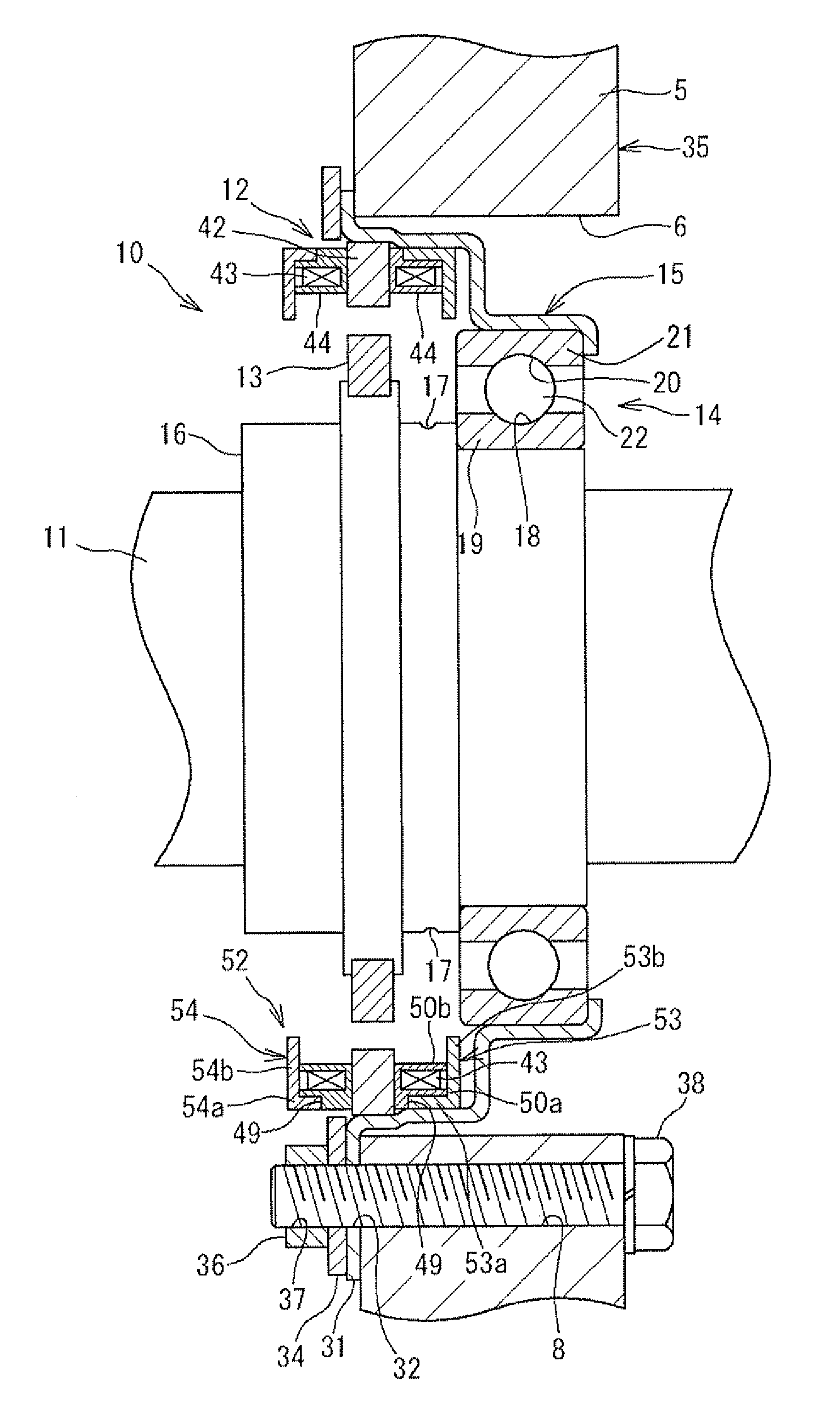
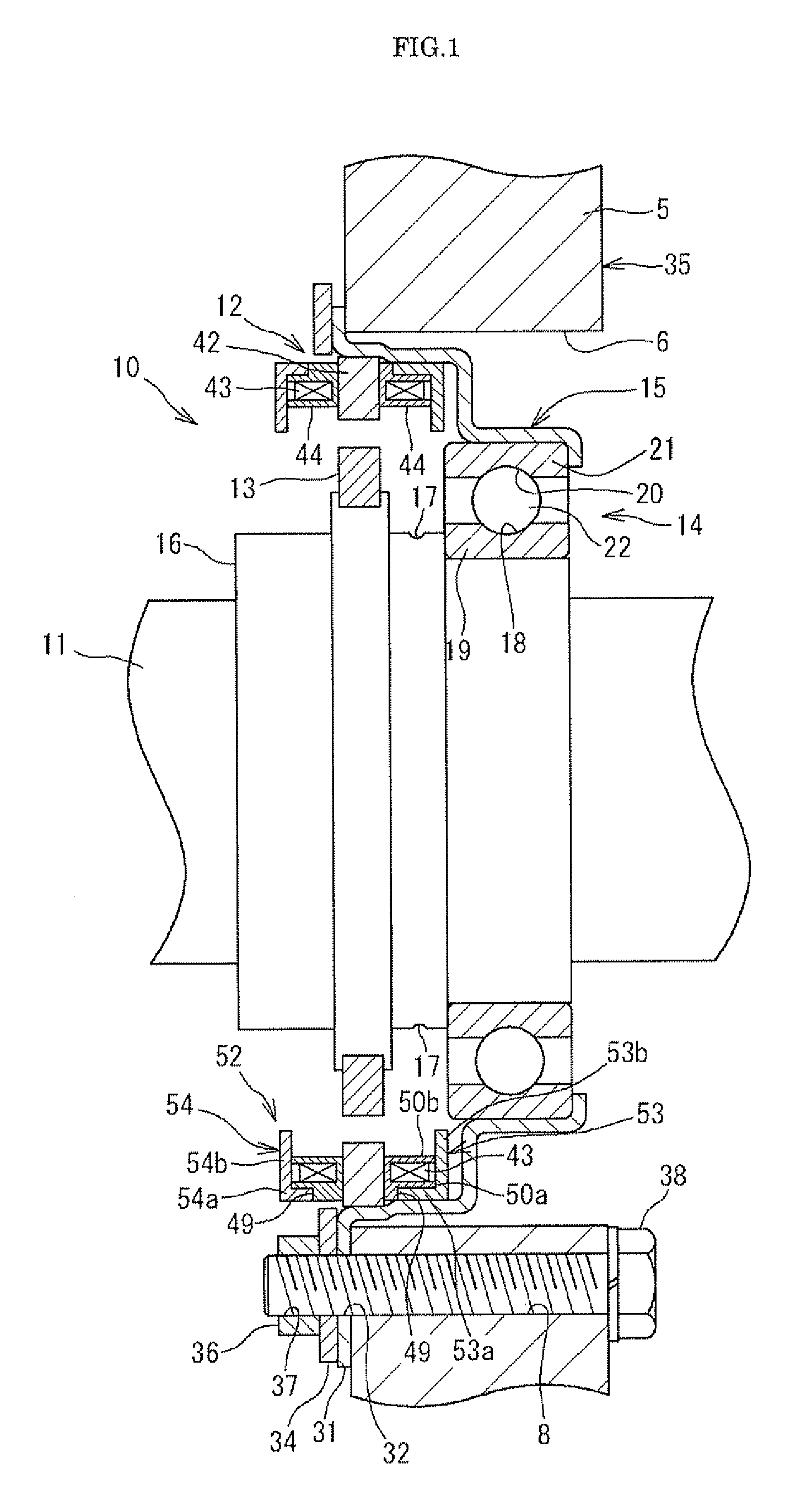
[0017]Embodiments of the invention will be described with reference to the accompanying drawings. FIG. 1 is a side sectional view that shows a resolver 10 according to a first embodiment of the invention. The resolver 10 according to the first embodiment is used to detect the rotation angle (rotational position) of a rotary shaft 11 of a motor generator used in a hybrid vehicle, for example. Although not shown in FIG. 1, a rotor of the motor generator is fixed to the rotary shaft 11 (at a position on the left side of the resolver 10 in an example shown in FIG. 1). In addition, the rotary shaft 11 is rotatably supported in a housing 35 by a rolling bearing 14 and a rolling bearing (not shown) that is provided at a position (at a position on the left side of the resolver 10 in the example shown in FIG. 1) apart from the rolling bearing 14 in the axial direction.

[0018]A motor stator (not shown) of the motor generator is fixed (at a position on the left side of the resolver 10 in the ex...


PUM


Abstract

A resolver stator includes an annular first cover portion, an annular second cover portion, and a plurality of pillars. The first and second cover portions cover coils from both axial sides. The pillars couple the first and second cover portions, and are arranged between the adjacent teeth. Each pillar has circumferential side faces each of which has a radially inner end portion that is arranged with a labyrinth clearance left between the radially inner end portion and a radially inner end portion of the tooth next to the side face, and each of which is a concave curved surface so as to be further apart from the tooth from the radially inner end portion toward a radially outer end portion of the side face.

Description

INCORPORATION BY REFERENCE[0001]The disclosure of Japanese Patent Applications No. 2011-160882 filed on Jul. 22, 2011 and No. 2012-106833 filed on May 8, 2012 including the specification, drawings and abstract, is incorporated herein by reference in its entirety.BACKGROUND OF THE INVENTION[0002]1. Field of the Invention[0003]The invention relates to a resolver that is used to detect the rotation angle (rotational position) of a rotary shaft.[0004]2. Description of Related Art[0005]A resolver is a type of angle detector used to detect the rotation angle (rotational position) of a rotary shaft, and includes a resolver stator and a resolver rotor. The resolver stator is formed into an annular shape, and is fixed at its outer periphery to a housing. In addition, multiple teeth are formed on the inner periphery of the resolver stator at predetermined intervals in the circumferential direction. Coils are wound around the respective teeth. The resolver rotor is arranged radially inward of ...

Claims


Application Information

Patent Timeline
IPC IPC(8): G01B7/30
CPCG01D11/245G01D5/2013
Inventor TAKEI, TOMOYUKIKITAHATA, KOUJIKUMENO, TOSHIKIHIGASHIYAMA, YOSHIMICHI
Owner JTEKT CORP
Why Eureka
Try Eureka