Flexible display with display support

a display and support technology, applied in the direction of identification means, electrical apparatus casings/cabinets/drawers, instruments, etc., can solve the problems of adding mechanical complexity, tearing of the display, and the open position of unsupported parts of the display, so as to improve the quality perception of the product, less likely to be damaged, and the display feels stiff

Active Publication Date: 2013-01-24
SAMSUNG ELECTRONICS CO LTD
View PDF10 Cites 340 Cited by
  • Summary
  • Abstract
  • Description
  • Claims
  • Application Information

AI Technical Summary

Benefits of technology

[0017]The advantages of the different embodiments are that in the open position the display is supported by an additional support when touched. This means that it is less likely to be damaged when touch functionality is added to the display. Another advantage is that the display will feel stiffer and gives a better quality perception of the product. The predefined curvature of the display segment in the closed position is advantageous for the lifetime of the display.

Problems solved by technology

For larger displays compared to the device body more turns are required, which adds mechanical complexity.
There are a lot of possibilities to realize the movement of the display with respect to the display system, but most of them result in an open position with unsupported parts of the display.
This can result in problems when touch functionality has to be integrated into the display.
The pressure from a touch on the display can result in tearing of the display due to the tensions and it can result in imprints along the edges of the unsupported display part.
Another problem is that for the end-user it is important to have a consistent feeling of touch across the whole display.
In an unsupported location, touching the display will feel different than in a supported location and this could be confusing to the end-user.

Method used


Image

  • Flexible display with display support
  • Flexible display with display support
  • Flexible display with display support

Examples


Embodiment Construction

[0030]Reference is made to applicant's Provisional Application Ser. No. 61 / 506,180, filed on Jul. 11, 2011, which is hereby incorporated by reference.

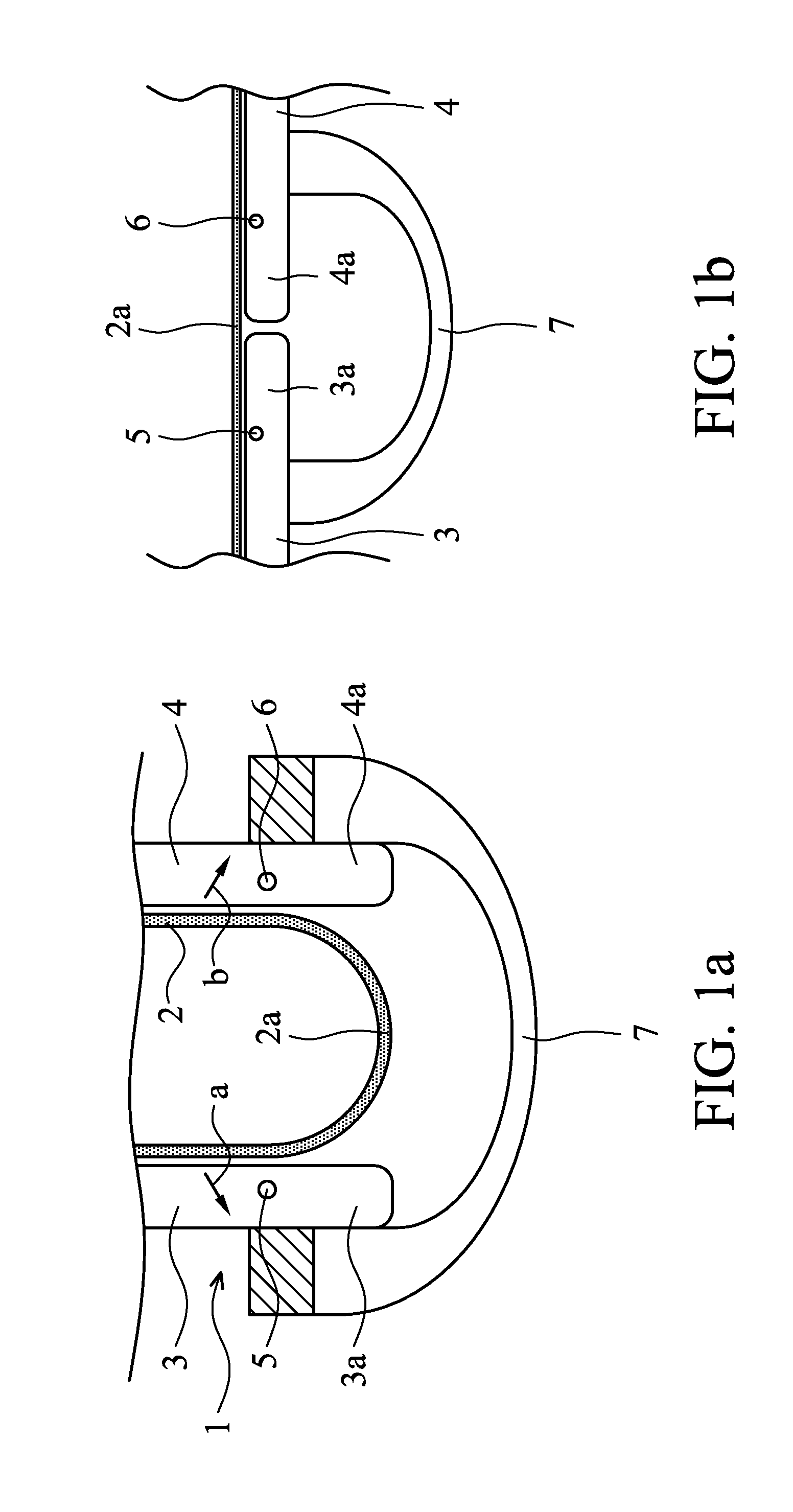
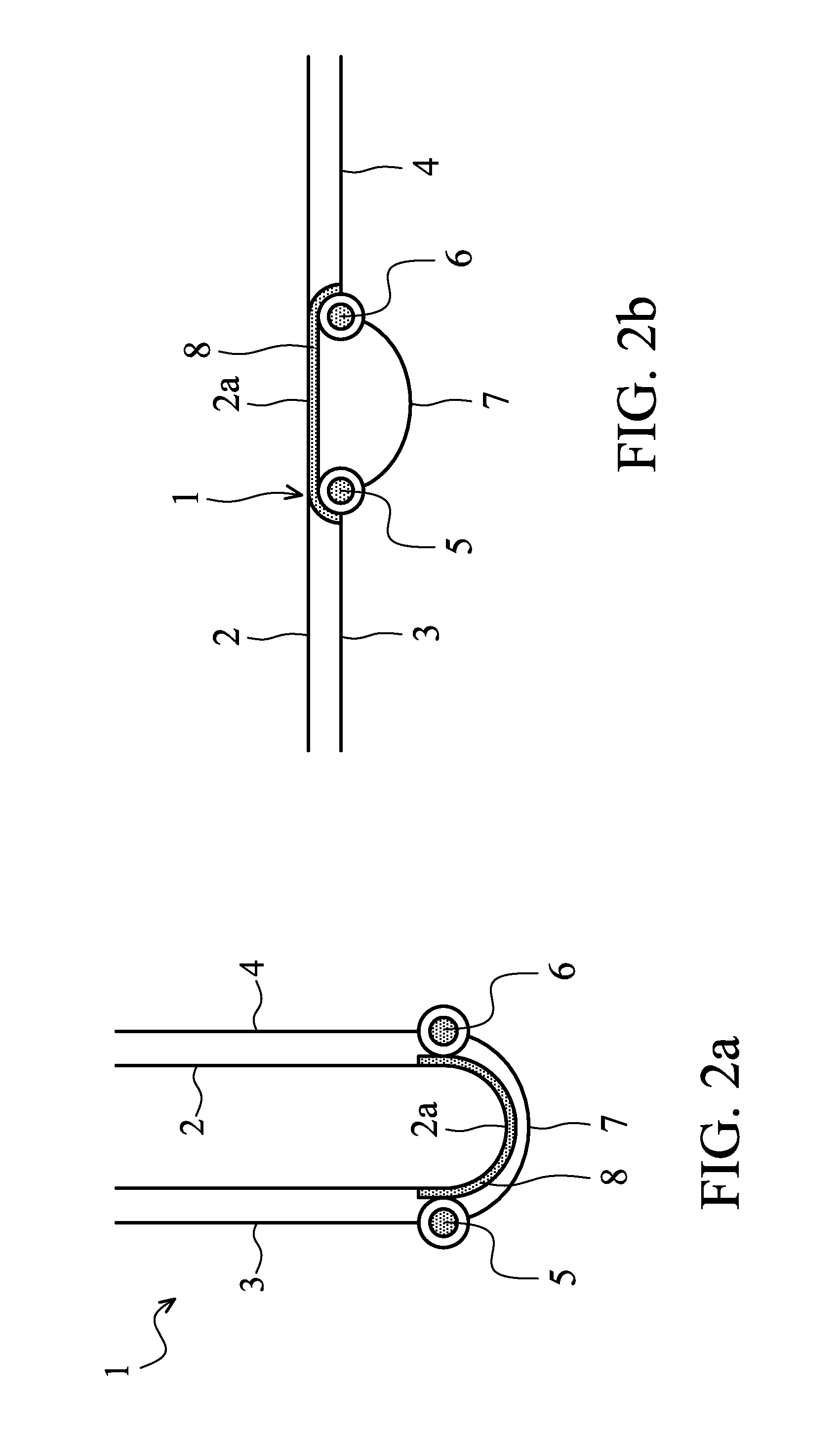
[0031]The display system 1 schematically shown in FIGS. 1A and 1B is a ‘wrap’ embodiment as disclosed in WO 2008 / 054206 A2 (herewith incorporated by reference). It comprises a flexible display 2 and a display support frame comprising two main display supports 3, 4. These supports 3, 4 are connected via hinges 5, 6 with a body 7 and are each structurally configured to support a respective portion of the flexible display 2. At the other side of the respective hinge 5, 6 each of the display supports 3, 4 show an elongated portion configuring an additional display support 3a, 4a. The two main display supports 3, 4 are rotatable in the direction of arrows a, b between a configuration shown in FIG. 1A for fixing the flexible display in a closed storage position and a planar configuration shown in FIG. 1B for fixing the flexible display in an...


PUM


Abstract

A display system includes a continuous flexible display and two main display supports being hingeable with respect to each other between a closed storage position and a planar configuration for fixing the flexible display in an open position. At least one additional display support supports a segment of the flexible display located between the said respective portions of the flexible display in the open position. This additional display support is movable with respect to the display segment between a non-operational position and a support position when the two main display supports are moved between the storage position and the planar position, such that in the open position substantially the whole surface of the display is supported by the respective display supports.

Description

[0001]This application claims the benefit of U.S. Provisional Application Ser. No. 61 / 506,177, filed on Jul. 11, 2011, which is hereby incorporated by reference.TECHNICAL FIELD[0002]The present invention generally relates to flexible displays. The present invention specifically relates to flexible displays provided with display supports.DESCRIPTION OF RELATED ART[0003]Flexible and especially rollable displays are manufactured on an organic substrate and are very thin. This makes it possible to repeatedly bend them with a small radius, a requirement for a rollable display. The advantages of a rollable display are the small volume needed for storing in the closed position and the lack of glass making the display unbreakable and of light weight.[0004]A number of product concepts have been developed for flexible displays. The most important concepts are the ‘book’, the ‘wrap’ and the ‘roll’. A ‘wrap’ concept is shown in WO 2008 / 054206 A2, a ‘roll’ concept in WO 2006 / 038171 Al. [0005]The...

Claims


Application Information

Patent Timeline
Patent Type & Authority Applications(United States)
IPC IPC(8): H05K7/00
CPCG06F1/1652G06F1/1681H04M1/0268H04M1/022G09F9/301H05K5/0017H05K5/0226
Inventor VAN DIJK, ROBERT SJANG JOSINEVERSCHOOR, VOLKER BARNHARTHAMERS, JOHANNES CORNELIS ADRIAANWALTERS, MICHAEL JOHANNES ANNA MARIAKRUIDHOF, RIK
Owner SAMSUNG ELECTRONICS CO LTD
Why Eureka
Try Eureka