Lamp and end cap for a lamp

a technology of end caps and lamps, which is applied in the field of lamps, can solve the problems of a significant hazard for the operator, a diode failure, and a risk to the person wishing to fit a lamp of such a kind into the holder, and achieve the effects of enhancing operating safety, avoiding risk, and enhancing safety

a technology of end caps and lamps, which is applied in the field of lamps, can solve the problems of a significant hazard for the operator, a diode failure, and a risk to the person wishing to fit a lamp of such a kind into the holder, and achieve the effects of enhancing operating safety, avoiding risk, and enhancing safety

US20130021809A1Inactive Publication Date: 2013-01-24LEDVANCE GMBH

Image

  • Lamp and end cap for a lamp
  • Lamp and end cap for a lamp
  • Lamp and end cap for a lamp

Examples


first embodiment

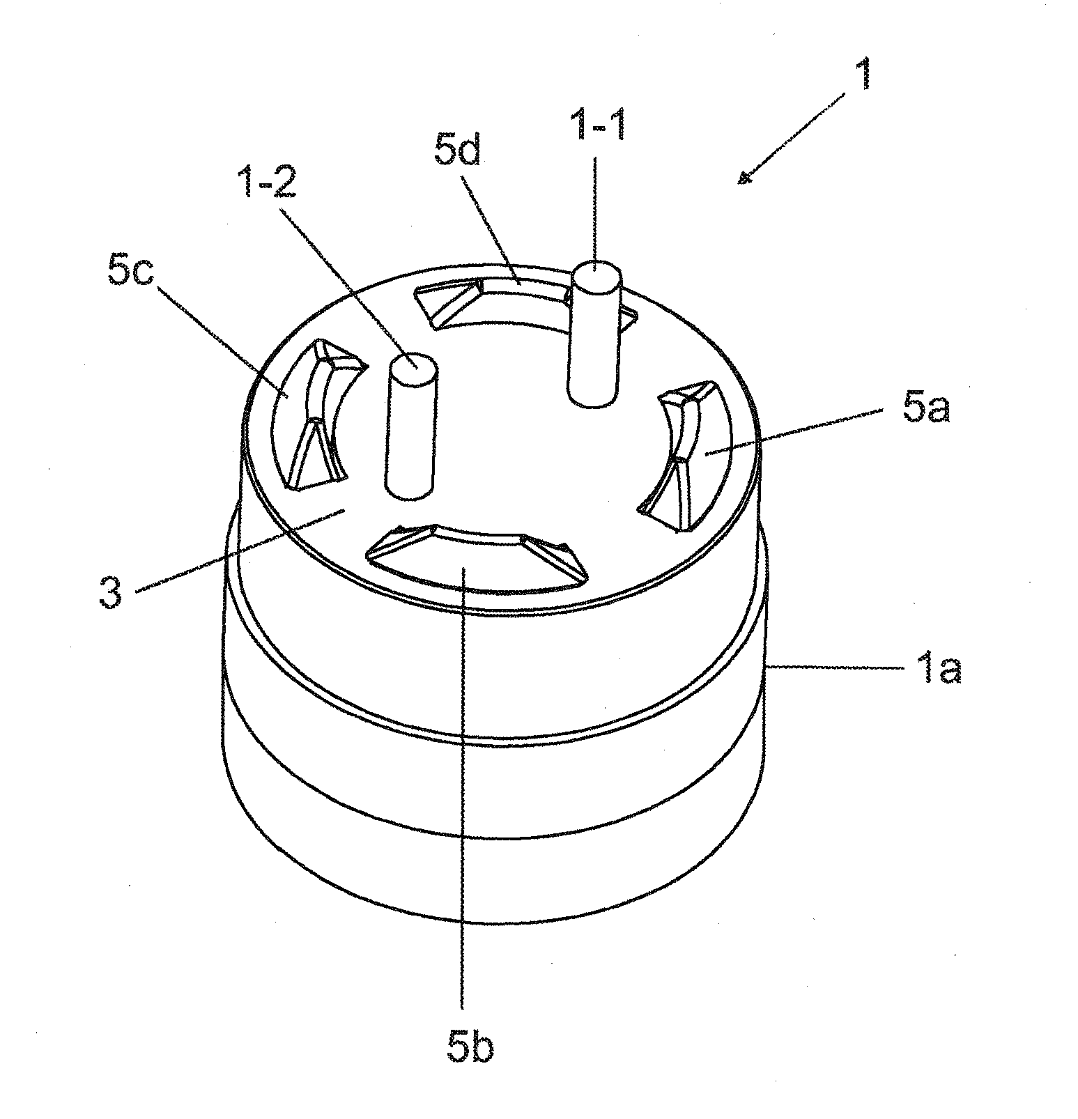
[0039]FIGS. 5, 6, and 7a-7d show an end cap 1 variant of the invention. End cap 1 can alternatively be referred to also as a base. End cap 1 has a substantially cylindrical housing section 1a with a circular end face / front face 3 from which two pins 1-1, 1-2 project axially. Housing section 1a can be made of, for example, plastic. The pins can alternatively be referred to as contact pins. Also projecting axially from front face 3 are four sensing elements 5a-5d that together form a sensing unit and which can be made of, for example, plastic. A correspondingly shaped opening is formed in front face 3 for each sensing element 5a-5d. Pins 1-1, 1-2 project further than sensing elements 5a-5d. Sensing elements 5a-5d all project equally. If the front face is divided into four 90° sectors (as indicated in FIG. 5 by the two dashed lines), then there will be a sensing element in each 90° sector. For example each sensing element is located centrally in its sector in the circumferential direc...

third embodiment

[0074]Arranged furthermore on the top side of plate 1c one behind the other in the circumferential direction are five radially inner electrically conductive sub-segments (not shown) that form a radially inner current path. The electrically conductive inner sub-segments can, for example, be accommodated in an inner circumferential slot (not shown). The inner sub-segments are arranged in exactly the same way as outer sub-segments 31a-31d, which is to say mutually overlapping with an axial spacing and having upwardly bent ring-arc segments in the overlapping region. As in the third embodiment variant, in each case one radially inner sub-segment and one radially outer sub-segment form a pair of sub-segments that are adjacent in the radial direction and the inner sub-segment and outer sub-segment of each pair extend substantially over the same angular range. When sensors 5a-5d are pushed axially downward, they push simultaneously axially against in each case an inner and an outer overlap...


PUM


Abstract

A rod-shaped retrofit lamp may have a mechanical sensing unit, and a current path has a plurality of electrically conductive sub-segments of which a first sub-segment is connected to the associated pin and of which a sub-segment is connected to the lamp's electronics unit, wherein the mechanical sensing unit is elastically pushed in counter to its projection direction from a released condition into an engaged condition and interacting with two current paths in such a way that the respective current path's first and second sub-segment will have been galvanically mutually coupled when the sensing unit is in the engaged condition so that the respective current path will have been closed and associated pin thereby electrically connected to the internal electronics unit.

Description

TECHNICAL FIELD[0001]The invention relates to a lamp, for example what is termed a retrofit lamp for fluorescent lamps, and to an end cap for a lamp.BACKGROUND[0002]Retrofit lamps having light-emitting diodes are known that can be fitted into existing luminaires as a replacement for the fluorescent lamps originally provided. For the known retrofit lamps it may, however, be necessary to modify the existing luminaire because said retrofit lamps cannot be operated on a specific existing conventional ballast for fluorescent lamps but are designed only for operation from an ac supply voltage. Known from US2008 / 0094837A1 is a retrofit lamp of such kind which, while being compatible with a conventional fluorescent lamp both mechanically and with regard to its holder, cannot be operated directly on a conventional ballast having a starter and not at all on an electronic operating device. For the retrofit lamp to be properly operated it is necessary to remove the original starter and bridge i...

Claims


Application Information

Patent Timeline
24 Jan 2013
Publication
US20130021809A1
IPC
F21V23/06
CPC
F21Y2101/02; H01R33/96; F21V23/06; F21K9/175; F21V25/04; F21Y2115/10; F21K9/272
Inventors
DELLIAN, HARALD; OTZEN, STEFAN