
X-ray device and method for controlling x-ray irradiation area using the same

Active Publication Date: 2013-01-24
SAMSUNG ELECTRONICS CO LTD
View PDF6 Cites 18 Cited by
  • Summary
  • Abstract
  • Description
  • Claims
  • Application Information

AI Technical Summary

Benefits of technology

The patent aims to improve the accuracy and ease of performing radiography by using an image to guide the patient's position and gesture in the radiation region. This also allows for faster imaging by controlling the patient's gesture based on the image.

Problems solved by technology

Such a method has a problem in that a structure, such as a visible light source disposed in the X-ray irradiation region control unit and a reflector to convert an irradiation direction of visible light into an irradiation direction of X-ray, is abnormally disposed, so visible light is irradiated to a region different from the region to which X-rays are irradiated and abnormal X-ray imaging is thus performed.
Also, this method has a problem in that imaging is performed in a wider region than required in order to avoid re-imaging due to the difficulty of accurate designation of an X-ray irradiation region and patients are thus exposed to irradiation of unnecessary X-rays from such re-imaging.

Method used


Image

  • X-ray device and method for controlling x-ray irradiation area using the same
  • X-ray device and method for controlling x-ray irradiation area using the same
  • X-ray device and method for controlling x-ray irradiation area using the same

Examples


Embodiment Construction

[0051]Reference will now be made in detail to preferred embodiments of the present invention, examples of which are illustrated in the accompanying drawings, wherein like reference numerals refer to like elements throughout.

[0052]Hereinafter, advantages and features of the preferred embodiments of the present invention and methods for accomplishing the same will be easily understood from the detailed description associated with preferred exemplary embodiments and the annexed drawings. However, one or more exemplary embodiments of the present invention may be realized in various forms and the exemplary embodiments described herein are not particularly limited.

[0053]In the following description, a detailed explanation of known related functions and constructions may be omitted to avoid unnecessarily obscuring the subject matter of the present invention. This invention may, however, be embodied in many different forms and should not be construed as limited to the exemplary embodiments ...


PUM


Abstract

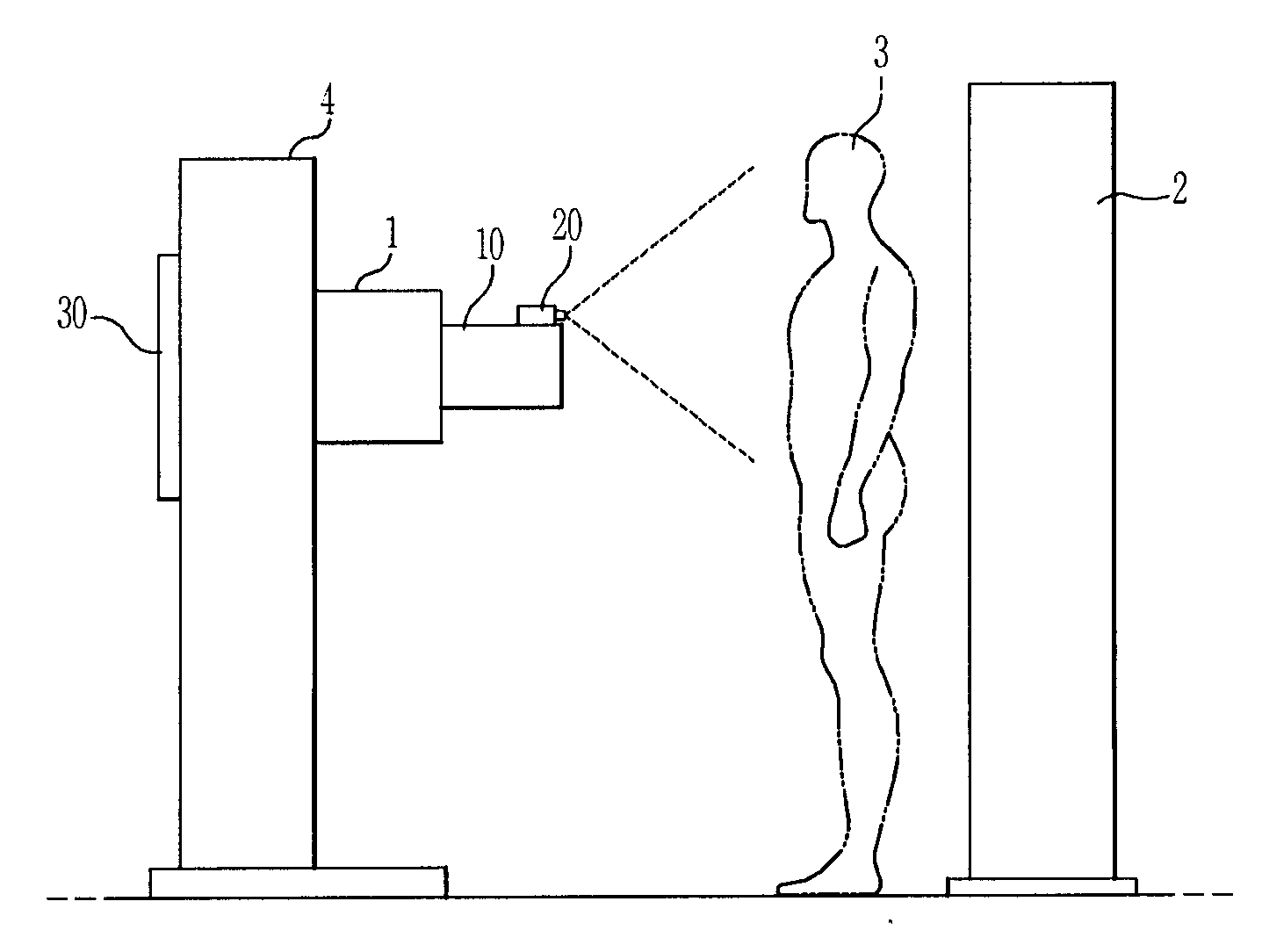
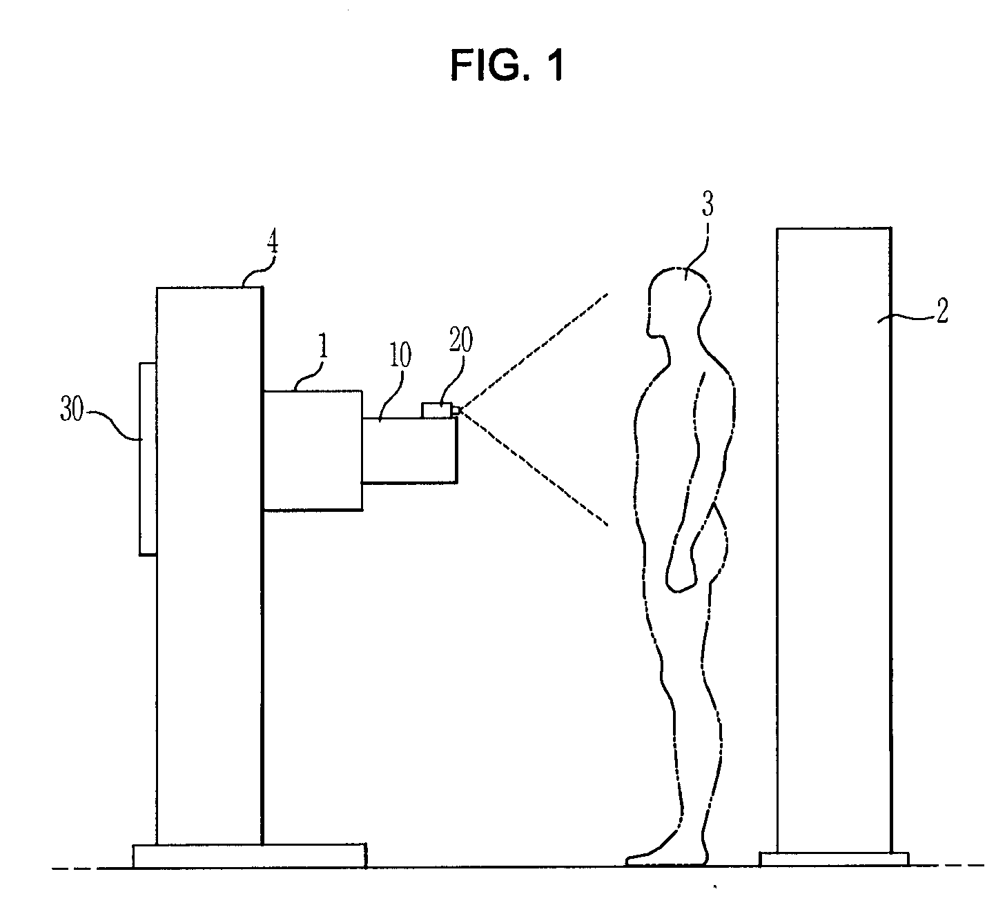
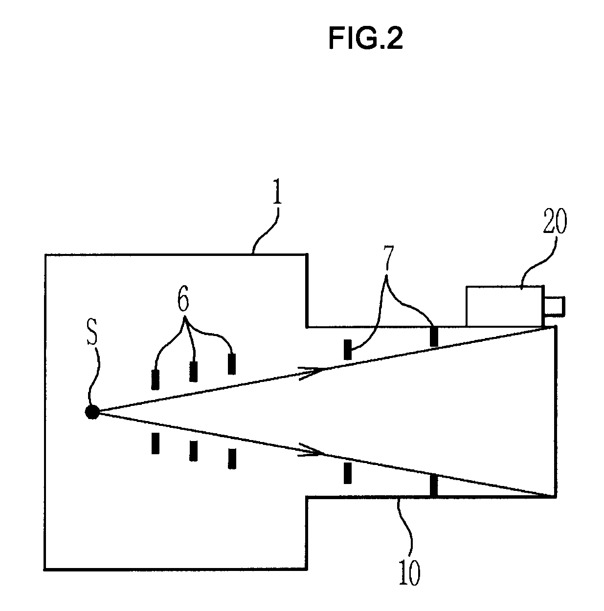
An X-ray device includes a camera to image an object and output the image of the object, a display member using a touch screen to display the image of the object output from the camera, and an X-ray irradiation region of the object, an X-ray irradiation region controller to control a region of the object to which an X-ray is irradiated, and a control member to enable the irradiation region controller to control the region of the object to which an X-ray is irradiated according to the X-ray irradiation region, when the X-ray irradiation region is determined, based on the image of the object displayed in the display member.

Description

CLAIM OF PRIORITY[0001]This application claims, pursuant to 35 U.S.C. 119(a), priority to and the benefit of the earlier filing date of Korean Patent Application Nos. 2011-0070932 and 2011-0116717, filed on Jul. 18, 2011 and Nov. 10, 2011, respectively, in the Korean Intellectual Property Office, the disclosures of which are incorporated herein by reference.BACKGROUND OF THE INVENTION[0002]1. Field of the Invention[0003]The present invention relates to an X-ray device including an X-ray irradiation region controller to control a region to which X-rays are irradiated, and a method for controlling the X-ray irradiation region using the X-ray device.[0004]2. Description of the Related Art[0005]An X-ray device is an apparatus for diagnosing diseases without incising the bodies of animals or patients by irradiating X-rays to animals or patients, detecting the X-rays transmitted into and through the bodies of animals or patients and thereby obtaining an image of an inner structure of the ...

Claims


Application Information

Patent Timeline
IPC IPC(8): G01N23/04
CPCA61B6/462A61B6/463A61B6/465A61B6/548A61B6/542A61N2005/1074A61B6/469A61B6/06A61B6/10A61B6/5229A61B6/5294A61B6/488A61B5/7435A61B5/7425H05G1/26
Inventor LEE, BYEONG WONMOON, JAE HWA
Owner SAMSUNG ELECTRONICS CO LTD
Learn More