Methods for repairing a turbine airfoil constructed from cmc material

a technology of cmc material and airfoil, which is applied in the direction of machines/engines, mechanical equipment, reaction engines, etc., can solve the problems of secondary damage and localized damage of the tip or cap of the rotating cmc airfoil

Inactive Publication Date: 2013-01-24
GENERAL ELECTRIC CO
View PDF4 Cites 16 Cited by
  • Summary
  • Abstract
  • Description
  • Claims
  • Application Information

AI Technical Summary

Problems solved by technology

After the airfoil is put into service, however, the tip or cap of the rotating CMC airfoil can experience localized damage as the tip or cap comes into contact with a gas turbine shroud or due to f

Method used


Image

  • Methods for repairing a turbine airfoil constructed from cmc material
  • Methods for repairing a turbine airfoil constructed from cmc material
  • Methods for repairing a turbine airfoil constructed from cmc material

Examples


Embodiment Construction

[0017]Reference now will be made in detail to embodiments of the invention, one or more examples of which are illustrated in the drawings. Each example is provided by way of explanation of the invention, not limitation of the invention. In fact, it will be apparent to those skilled in the art that various modifications and variations can be made in the present invention without departing from the scope or spirit of the invention. For instance, features illustrated or described as part of one embodiment can be used with another embodiment to yield a still further embodiment. Thus, it is intended that the present invention covers such modifications and variations as come within the scope of the appended claims and their equivalents.

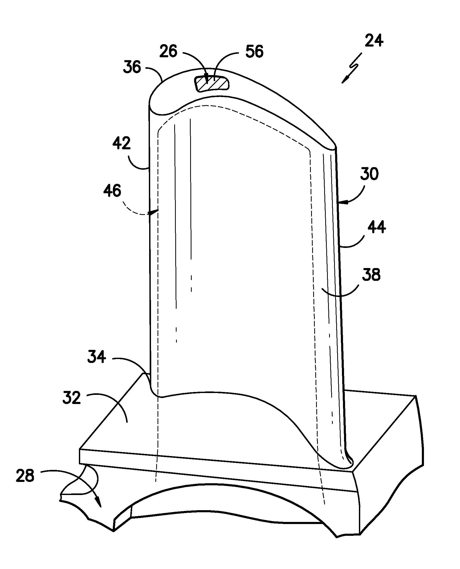
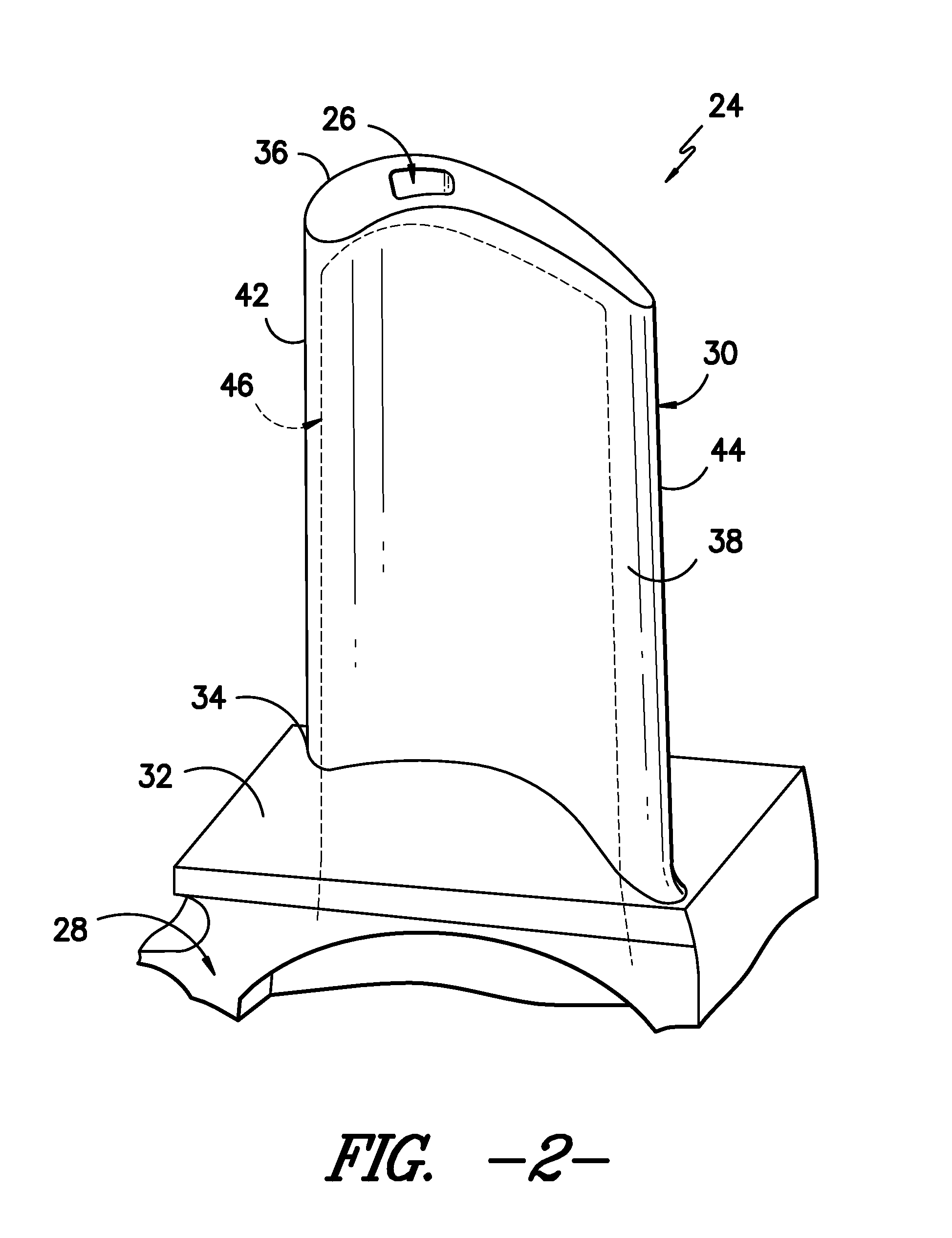
[0018]In general, methods are generally provided for repairing an article (e.g., a tip or cap of an airfoil in a gas turbine), along with the resulting repaired article (e.g., repaired airfoils). In particular, methods are generally provided for repairing a...


PUM

PropertyMeasurementUnit
Temperatureaaaaaaaaaa

Abstract

Methods for repairing a turbine airfoil constructed from a CMC material are provided via filling a cavity located in the turbine airfoil with a ceramic paste (e.g., including a ceramic powder and a binder), heating the ceramic paste in the cavity to remove the binder, thereby forming a porous ceramic material, and adding a molten ceramic material to the porous ceramic material. The cavity can be defined in an airfoil of the turbine airfoil (e.g., on a tip or cap of the airfoil). Intermediates formed during the repair of a turbine airfoil are also provided. The intermediate can generally include an airfoil comprising a CMC material, a cavity defined in the airfoil, and a porous ceramic material filling the cavity.

Description

FIELD OF THE INVENTION[0001]The present subject matter relates generally to repairing tips or caps for turbine airfoils and, more particularly, to a ceramic-based tip or cap repair for a turbine airfoil.BACKGROUND OF THE INVENTION[0002]In a gas turbine, air is pressurized by a compressor and then mixed with fuel and ignited within an annular array of combustors to generate hot gases of combustion. The hot gases flow from each combustor through a transition piece for flow along an annular hot gas path. Turbine stages are typically disposed along the hot gas path such that the hot gases flow through first-stage nozzles and airfoils and through the nozzles and airfoils of follow-on turbine stages. The turbine airfoils may be secured to a structural case or a plurality of rotor disks comprising the turbine rotor, with each rotor disk being mounted to the rotor shaft for rotation therewith.[0003]A turbine airfoil generally includes an airfoil extending radially outwardly from a substanti...

Claims


Application Information

Patent Timeline
IPC IPC(8): F01D5/14B05D3/00B05D1/38B05D7/22B05D3/02
CPCF01D5/005Y10T29/49318F01D5/284F05D2300/6033C04B41/89C04B41/009C04B41/52F01D5/282F01D5/147C04B35/80C04B41/4539C04B41/4572C04B41/4582C04B41/5025C04B14/4693C04B41/5059C04B41/522C04B41/4523
Inventor ROBERTS, III, HERBERT CHIDSEYGRAY, PAUL EDWARDMATSUMOTO, ROGER LEE KENBOY, JEFFREY H.MONAGHAN, PHILIP HAROLDHALADA, JOSEPH
Owner GENERAL ELECTRIC CO
Why Eureka
Try Eureka