Sewage Pumping System and Method

a technology of pumping system and liquid level, applied in the direction of pump control, non-positive displacement fluid engine, pump control, etc., can solve the problem of often unsuitable visual readings

Active Publication Date: 2013-01-24
SJE RHOMBUS
View PDF5 Cites 25 Cited by
  • Summary
  • Abstract
  • Description
  • Claims
  • Application Information

AI Technical Summary

Benefits of technology

[0008]An exemplary method is also provided. The method includes determining that liquid in a reservoir is at a first level, and through operation of at least one controller, causing a pump to operate at substantially the lowest usage of energy to move liquid out of the reservoir from the first level to a second level in response to the liquid being at the first level.

Problems solved by technology

Visual readings, however, are often not desirable in systems where an automatic response is required when the liquid level reaches a certain threshold.

Method used


Image

  • Sewage Pumping System and Method
  • Sewage Pumping System and Method
  • Sewage Pumping System and Method

Examples


Embodiment Construction

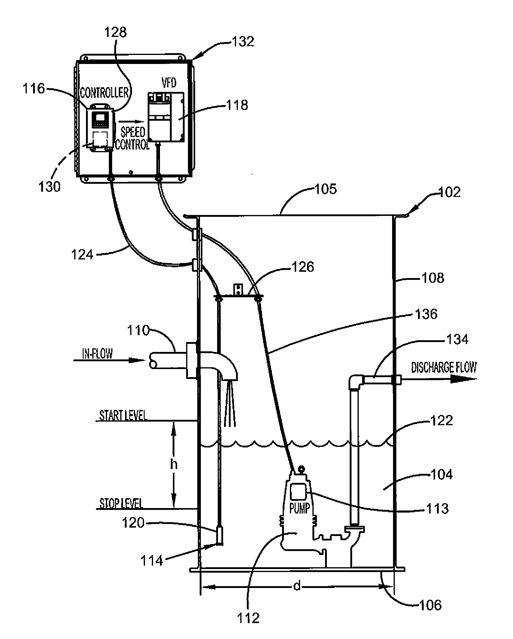
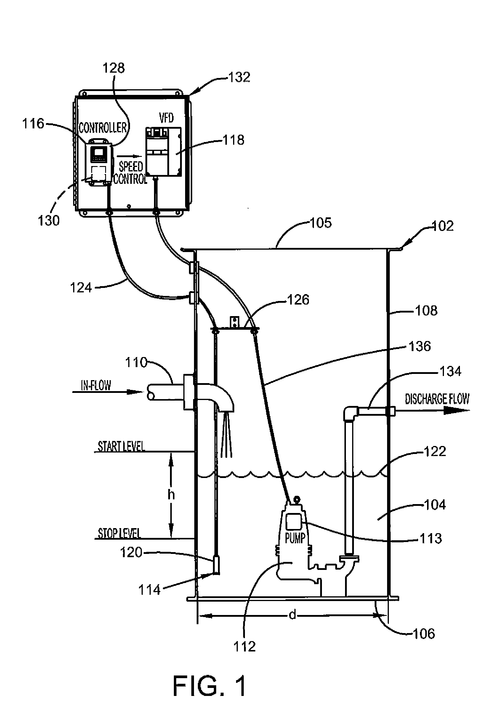
[0013]Various technologies pertaining to an example system that facilitates monitoring and control of a depth level of a liquid in a reservoir will now be described with reference to the drawings, where like reference numerals represent like elements throughout. In addition, several functional block diagrams of example systems are illustrated and described herein for purposes of explanation; however, it is to be understood that functionality that is described as being carried out by certain system components may be performed by multiple components. Similarly, for instance, a component may be configured to perform functionality that is described as being carried out by multiple components.

[0014]FIG. 1 shows an exemplary embodiment of a sewage pumping system 100 that facilitates monitoring and control of a depth level of a liquid in a reservoir. The system 100 may include a reservoir 102 capable of holding a liquid 104 therein. Such a liquid may include many different types of fluids ...


PUM


Abstract

A system includes a pump that is operative to move liquid out of a reservoir. The system also includes a depth level sensor that is operative to determine a depth level of the liquid in the reservoir, and a controller operatively connected to the depth level sensor. The system further includes a variable frequency drive operatively connected to the motor and the controller. Responsive to the determined depth level of the liquid increasing to a first level, the controller is operative to start operation of the motor. The variable frequency drive is operative to control the speed of the motor. The controller is operative to cause the variable frequency drive to output an optimum frequency that causes the motor to operate at substantially the lowest usage of energy to lower the depth level of the liquid in the reservoir from the first level to a second level.

Description

CROSS-REFERENCE TO RELATED APPLICATIONS[0001]This application claims benefit under 35 U.S.C. §119(e) of Provisional Application No. 61 / 509,020 filed Jul. 18, 2011, the disclosure of which is incorporated herein by reference in its entirety.BACKGROUND[0002]The present invention relates to systems that control levels of liquids in reservoirs. Specifically this invention relates to liquid level sensing and control systems for wastewater systems.[0003]It is often desirable to know information about liquid levels in tanks. Determining liquid levels and controlling liquid levels in reservoirs, such as in sewage tanks, wells, water cisterns or tanks, and other liquid systems and storage vessels, whether enclosed or open and exposed to the environment, has been done in a number of ways. For example, in tanks that are visually accessible, an operator may periodically take visual readings of the liquid level.[0004]Visual readings, however, are often not desirable in systems where an automatic...

Claims


Application Information

Patent Timeline
Patent Type & Authority Applications(United States)
IPC IPC(8): F04B49/06
CPCF04B23/023F04B23/021F04B49/06F04B49/065F04D13/08F04D13/086F04D15/0066F04D27/004
Inventor ATCHIA, ALAIN JULIAN
Owner SJE RHOMBUS
Why Eureka
Try Eureka