Tracking of tumor location for targeted radiation treatment

Active Publication Date: 2013-01-24
HEADWATER PARTNERS I
View PDF3 Cites 11 Cited by
  • Summary
  • Abstract
  • Description
  • Claims
  • Application Information

AI Technical Summary

Benefits of technology

This patent describes a system that allows a patient to move around during radiation treatment without being restricted to a specific position. This is done by attaching sensors to the patient's body and using scans, such as MRI or CT, to determine the location of the tumor relative to the markers on the patient's body. A mapping model is then created from these markers to outline the tumor's location. The patient can choose their natural position during treatment, and the model can be adjusted based on the patient's characteristics and scans from other patients. This system also uses sensors on the beam to accurately determine its position, which can save time and money and improve treatment accuracy.

Problems solved by technology

Errors may arise from delays in detecting positions of markers, calculating tumor locations from the marker positions, determining an optimal beam trajectory, and moving the radiation beam to an optimal location.

Method used


Image

  • Tracking of tumor location for targeted radiation treatment
  • Tracking of tumor location for targeted radiation treatment
  • Tracking of tumor location for targeted radiation treatment

Examples


Embodiment Construction

I. Introduction

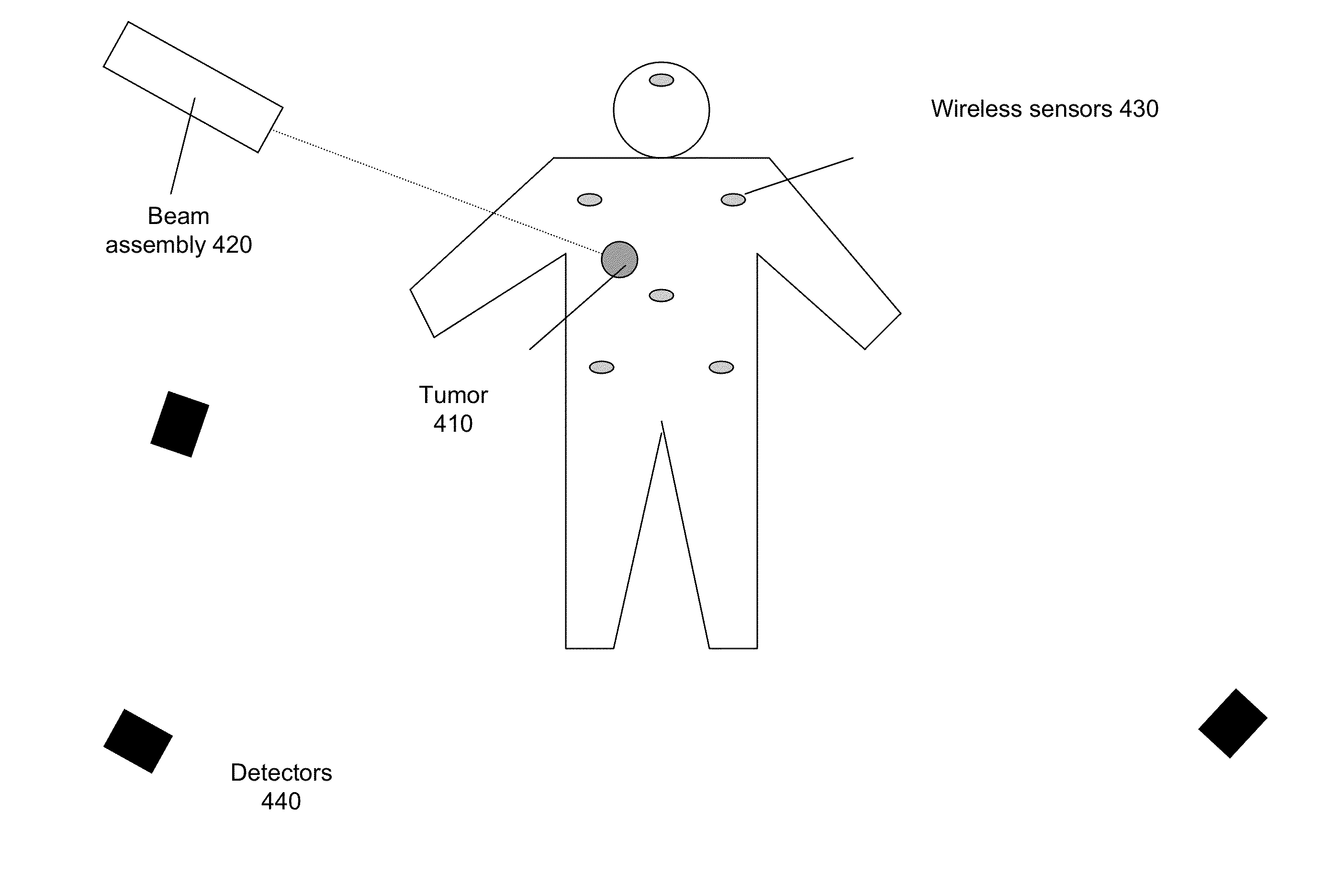
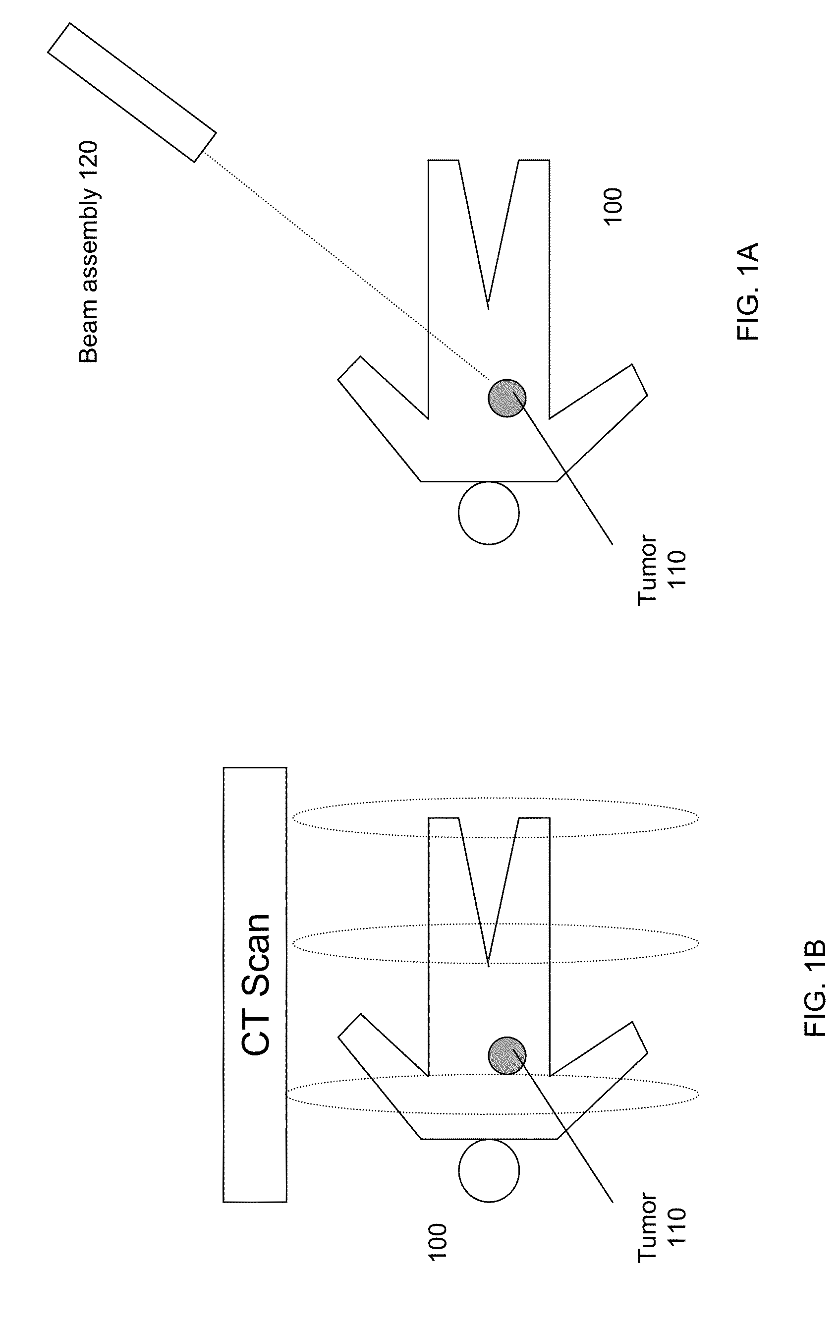
[0029]FIG. 1 shows a diagram of a patient 100 undergoing radiation beam treatment according to embodiments of the present invention. The patient 100 is shown as laying down on his / her back, but other body positions and orientations are allowed. A beam assembly 120 is shown in a particular orientation to provide a radiation beam 130 that is focused on a tumor 110 inside patient 100. Beam assembly 120 can be connected to a movement mechanism that allows beam assembly 120 to be moved. For example, beam assembly 120 can be part of a robotic mechanism that sits on a floor of a room, is attached to a wall, or hangs from a ceiling.

[0030]In one embodiment, beam assembly 120 may be moved during treatment so that healthy tissue is not irradiated for too long. For example, if the beam always had the same trajectory, the tissue above the tumor 110 would continuously be exposed to radiation. If the beam assembly moved while staying focused, the same healthy tissue would not be con...


PUM


Abstract

Systems, methods, and apparatuses are provided for targeting diseased tissue with a radiation beam. Functional models can be used to accurately obtain a location of specific tissue using sensors at identifiable locations of the patient's body. Using the relative distances between the identifiable sensor locations can allow a patient to be in various positions. The functional models can be prepared using accurate pre-treatment scans, which can be taken at various body positions (e.g., rotations and / or translations). The trajectory of the beam can be measured efficiently and accurately using beam sensors attached to a beam assembly, where a model maps the beam sensor locations to a trajectory of the beam. Further, a motion model can use measurements made during treatment to obtain a time-dependent functions of the movement of the specific tissue, the change of an optimal beam trajectory over time, or the change in input commands to a beam positioner.

Description

CROSS-REFERENCES TO RELATED APPLICATIONS[0001]The present application claims priority from and is a non-provisional application of U.S. Provisional Application No. 61 / 435,195, entitled “Non-Invasive Tracking of Tumor Location for Targeted Radiation Treatment” filed Jan. 21, 2011, the entire contents of which are herein incorporated by reference for all purposes.BACKGROUND[0002]The present invention relates to targeted radiation treatment (also called radiosurgery), and more specifically to techniques of determining a location of a tumor or other diseased tissue for determining a trajectory of a radiation beam.[0003]Radiation beams have been used to kill diseased tissue (e.g. a tumor). However, the radiation beam can also kill healthy tissue. Thus, methods have been used to determine a location of a tumor so that the radiation beam can be focused on the tumor. For example, the radiation beam can move over time to minimize exposure of healthy tissue while staying focused on the tumor....

Claims


Application Information

Patent Timeline
IPC IPC(8): A61N5/10
CPCA61N5/1037A61N2005/1061A61N5/1049A61N5/1039A61N5/1067A61N5/1069A61N5/1077A61N2005/1051
Inventor RALEIGH, GREGORYRAISSINIA, ALIREZA
Owner HEADWATER PARTNERS I
Why Eureka
Try Eureka