
Autonomous Electronic Device and Method of Controlling Motion of the Autonomous Electronic Device Thereof

a technology of autonomous electronic devices and electronic devices, which is applied in the direction of process and machine control, distance measurement, instruments, etc., can solve the problems of increasing manufacturing costs, adding difficulty in device design, and height limits of contact sensors and non-contact sensors of autonomous electronic devices in the prior ar

Inactive Publication Date: 2013-01-24
EMEME ROBOT
View PDF15 Cites 8 Cited by
  • Summary
  • Abstract
  • Description
  • Claims
  • Application Information

AI Technical Summary

Benefits of technology

The present invention provides an autonomous electronic device with a motion sensor module that can detect the surrounding conditions and control the movement of the device accordingly. The device includes a motor, wheel, and processing module that work together with the motion sensor module to adjust the wheel to the surrounding conditions. This invention allows for improved navigation and adaptability of the autonomous electronic device to its surroundings.

Problems solved by technology

However, to allow the autonomous electronic device of the prior art to work better, the autonomous electronic device must comprise both a contact sensor and a non-contact sensor, which adds difficulty to design the device and increases the manufacturing cost.
On the other hand, there is a height limit for the contact sensor and the non-contact sensor of the autonomous electronic device in the prior art; for example, if the height of obstacle is lower than the main body of the autonomous electronic device, or the obstacle is higher than the height of the bumper, the autonomous electronic device of the prior art may fail to avoid the obstacle.
Furthermore, while moving across an uneven surface, the autonomous electronic device of the prior art cannot adjust its movement immediately according to surrounding conditions.

Method used


Image

  • Autonomous Electronic Device and Method of Controlling Motion of the Autonomous Electronic Device Thereof
  • Autonomous Electronic Device and Method of Controlling Motion of the Autonomous Electronic Device Thereof
  • Autonomous Electronic Device and Method of Controlling Motion of the Autonomous Electronic Device Thereof

Examples


first embodiment

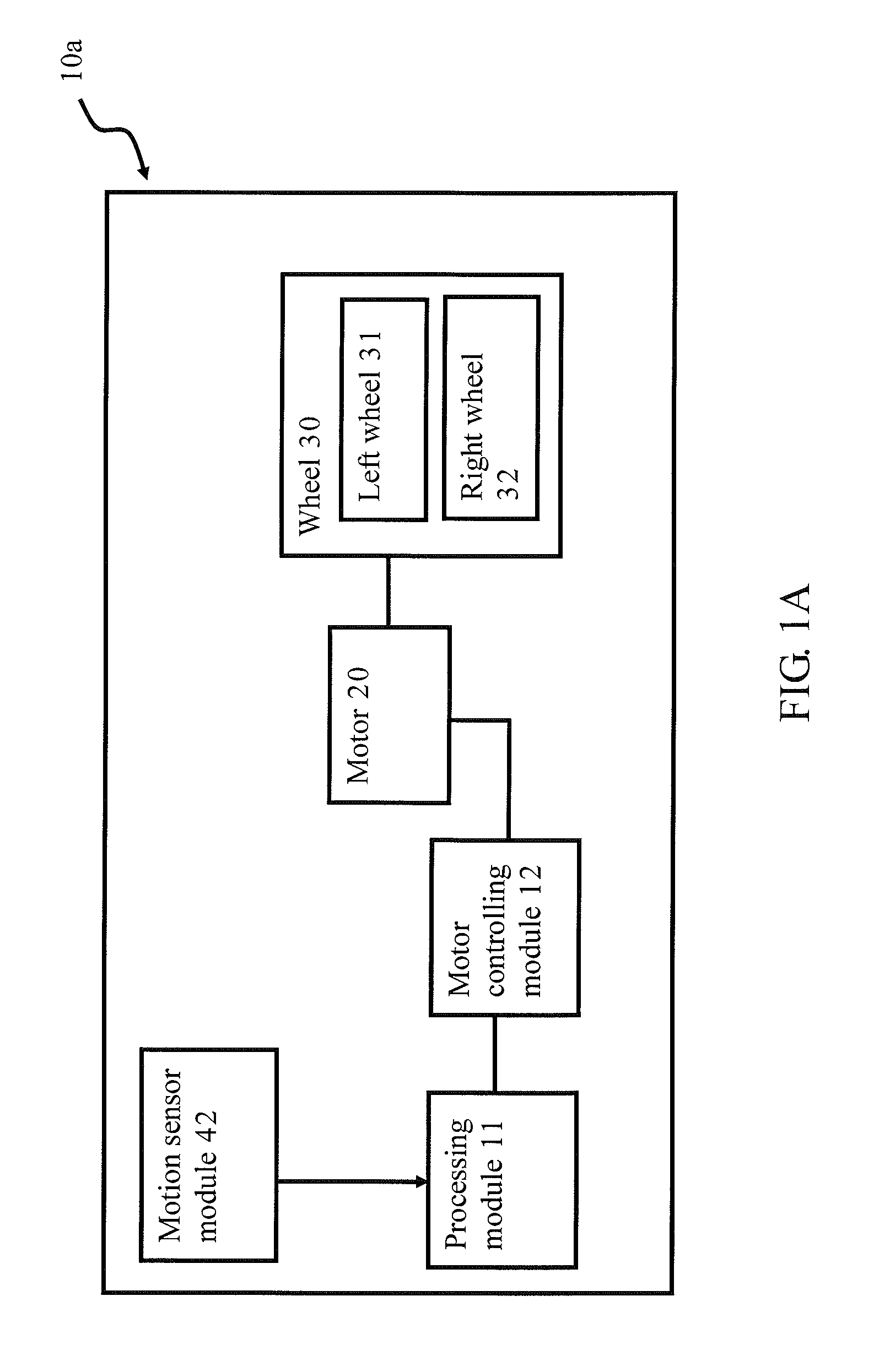
[0019]Please refer to FIG. 1A, which illustrates a system structure drawing of the autonomous electronic device according to the present invention.

[0020]In the first embodiment of the present invention, the autonomous electronic device 10a is an automatic cleaning robot, but the present invention is not limited to that application. The autonomous electronic device 10a comprises a processing module 11, a motor controlling module 12, a motor 20, a wheel 30, and a motion sensor module 42. The processing module 11 and the motor controlling module 12 can be software, firmware, hardware, or a firmware with hardware, but the present invention is not limited to that design. The processing module 11 is used for controlling the function within the autonomous electronic device 10a. The motor controlling module 12 is connected electrically to the processing module 11, which controls the motor 20 via the motor controlling module 12. The motor 20 connected to the wheel 30 is used for controlling ...

second embodiment

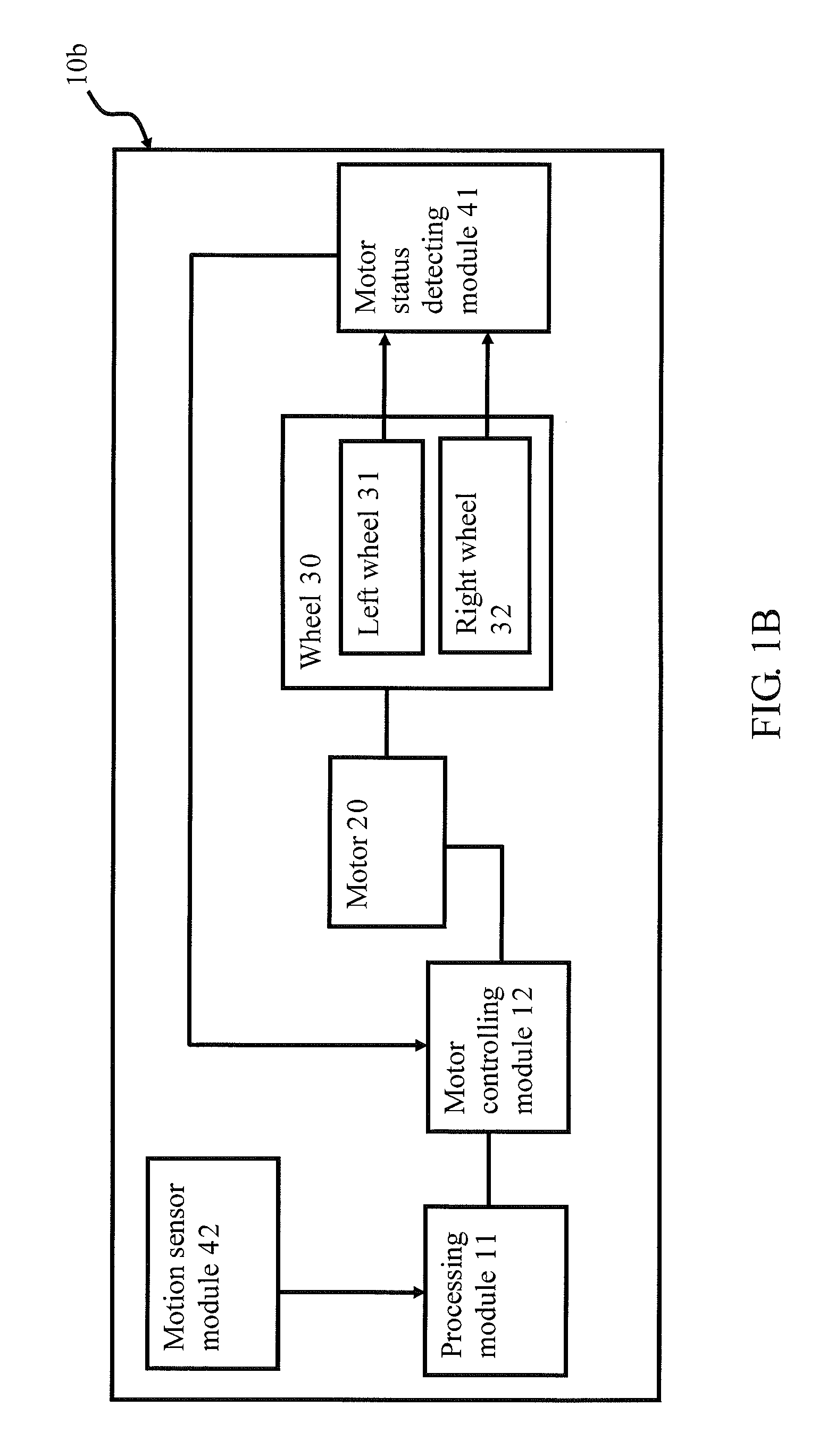
[0024]Please refer to FIG. 1B, which illustrates a system structure drawing of the autonomous electronic device according to the present invention.

[0025]The second embodiment of the present invention is the best embodiment of the present invention. In the second embodiment of the present invention, the autonomous electronic device 10b includes a processing module 11, a motor controlling module 12, a motor 20, a wheel 30, a motor status detecting module 41, and a motion sensor module 42. The processing module 11 is used for controlling the function within the autonomous electronic device 10b. The motor controlling module 12 is connected electrically to the processing module 11, the processing module 11 controls the motor 20 via the motor controlling module 12. The motor 20, connected to the wheel 30, is used for controlling the rotation speed and direction.

[0026]The autonomous electronic device 10b comprises both the motor status detecting module 41 and the motion sensor module 42. T...

third embodiment

[0056]Please refer the FIG. 6, which illustrates a flowchart drawing of the method for adjusting the motor of the autonomous electronic device according to the present invention.

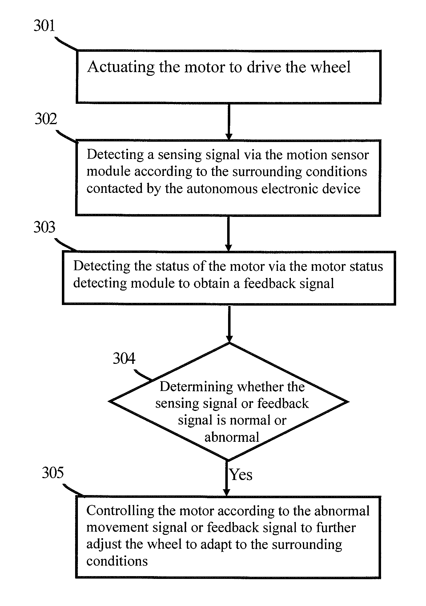
[0057]In the third embodiment, the processing module 11 first executes step 601: Determining whether the feedback signal is over a specific threshold or the sensing signal of the vertical axis is over a vibration threshold.

[0058]According to the sensing signal transferred from the motion sensor module 42, the processing module 11 can determine whether the sensing signal of the vertical axis is over a vibration threshold. The vibration threshold can be the vertical axis acceleration change value of the autonomous electronic device 10b in normal movement. On the other hand, according to the feedback signal generated by the motor status detecting module 41, the processing module 11 can determine whether the feedback signal is over a specific threshold. Taking the electric current value of the motor 20 detected ...


PUM


Abstract

An autonomous electronic device and a method of controlling the motion of the autonomous electronic device thereof are disclosed. The autonomous electronic device includes a motor, a wheel, a processing module, a motor controlling module, and a motion sensor module. The motor is used for driving the wheel. The motor controlling module is used for controlling the motor. The motion sensor module is used for generating a sensing signal according to surrounding conditions encountered by the autonomous electronic device and transferring the signal to the processing module, wherein when the sensing signal is an abnormal movement signal, the processing module controls the motor to adapt to the surrounding conditions via the motor controlling module according to the abnormal movement signal.

Description

BACKGROUND OF THE INVENTION[0001]1. Field of the Invention[0002]The present invention relates to an autonomous electronic device and a method of controlling the motion of the autonomous electronic device thereof; more particularly, the present invention relates to an autonomous electronic device that uses a motion sensor module to detect the surrounding conditions and a method of controlling the motion of the autonomous electronic device thereof.[0003]2. Description of the Related Art[0004]As technology develops, autonomous electronic devices, also known as robots, are applied widely to automatically execute cleaning work. However, in the prior art, to prevent the autonomous electronic device from hitting an obstacle or a wall, a contact sensor or a non-contact sensor is located on the autonomous electronic device. The non-contact sensor uses infrared rays or laser to transmit signals to detect the distance from the obstacle to itself. In order to reduce the blind spots in its detec...

Claims


Application Information

Patent Timeline
Patent Type & Authority Applications(United States)
IPC IPC(8): G05D1/00
CPCG05D2201/0203G05D1/027
Inventor CHIU, HUNG-CHIHCHUANG, CHUNG-HSIENLIN, CHI-SHINGHSU, HARRY CHIA-HUNG
Owner EMEME ROBOT
Learn More