
Methods for optimizing data movement in solid state devices

a solid state device and data movement technology, applied in the direction of memory adressing/allocation/relocation, instruments, computing, etc., can solve the problems of wasting power, blocking other user operations, and referring to the cost and cost of reading and writing data as “expensive” in terms of device performance, so as to achieve the effect of optimizing data movemen

Active Publication Date: 2013-01-24
WESTERN DIGITAL TECH INC
View PDF5 Cites 30 Cited by
  • Summary
  • Abstract
  • Description
  • Claims
  • Application Information

AI Technical Summary

Benefits of technology

The patent text describes techniques for optimizing data movement in electronic storage devices. These techniques involve maintaining a data structure on the device that associates virtual memory addresses with physical memory addresses. The information about this data structure can be provided to the host through a Logical Block Number translation query command. The host can modify the data structure by receiving a command to add or remove pointers. The techniques can be implemented in electronic storage devices such as solid state devices, hard drives, and RAID arrays. The patent also mentions that the host can request a memory freeing operation to free memory sizes of different levels of granularity. The data structure can include key-value pairs, journal log entries, and version data. Overall, the techniques described in the patent text allow for efficient data movement and management in electronic storage devices.

Problems solved by technology

There are several disadvantages associated with this process of reading from the device, buffering on the host, and writing data to the host.
These disadvantages are reasons why reading and writing data is referred to as “costly” or “expensive” in terms of device performance.
Because the host is involved in every step of the process, this process occupies the central processing unit (CPU) of the host, wastes power, blocks other user operations that otherwise could have been performed, and requires that the host contain a buffer to store read data.
This means that a page of memory may take ten times as long to be erased as to be written.

Method used


Image

  • Methods for optimizing data movement in solid state devices
  • Methods for optimizing data movement in solid state devices
  • Methods for optimizing data movement in solid state devices

Examples


Embodiment Construction

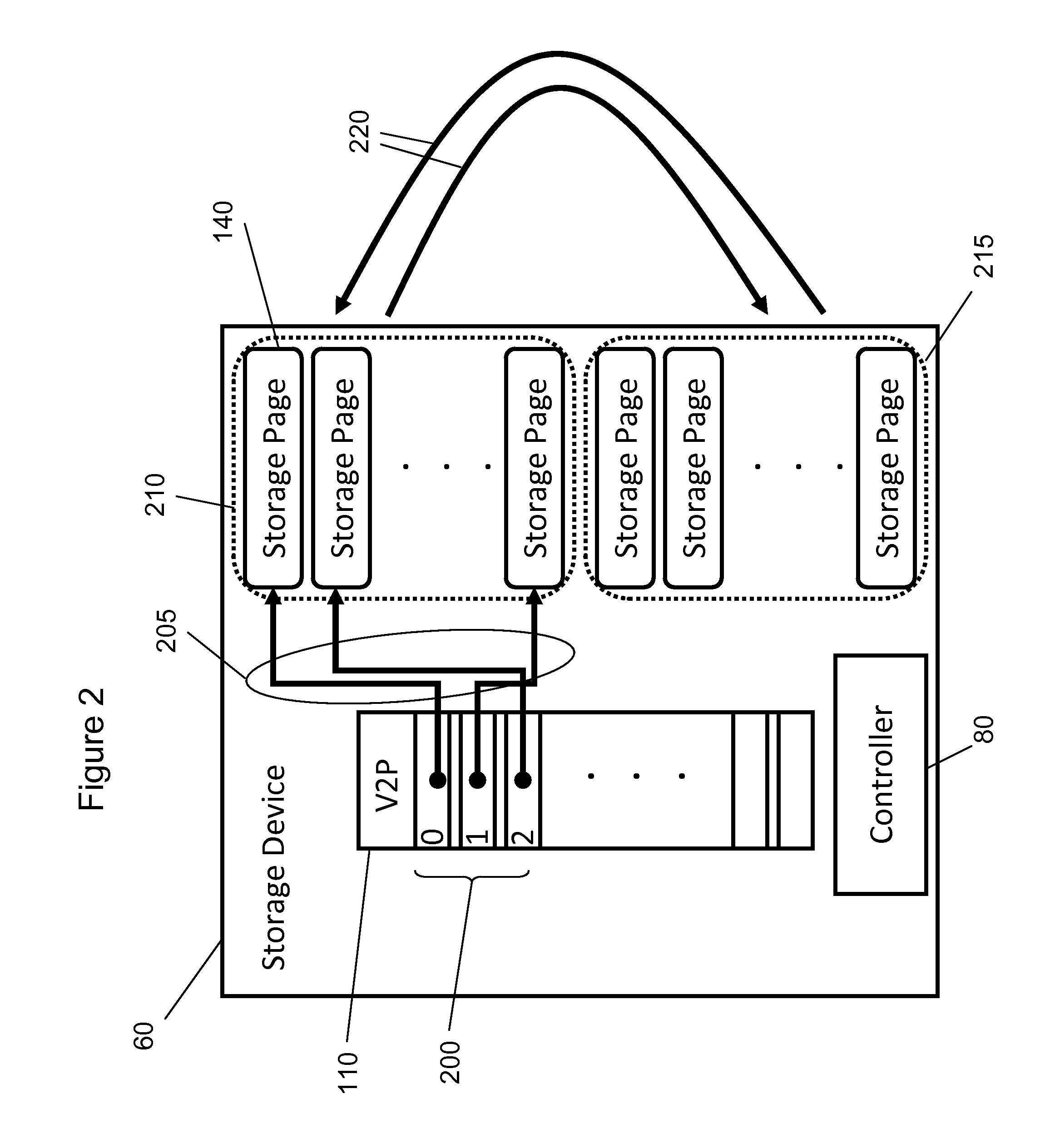
[0039]The present disclosure relates to a series of commands that allow a host to manipulate a set of pointers, where the set of pointers point to data that reside in a memory device, for example, a solid state device (SSD). The commands are implemented by the memory device which makes the commands available for use by the host software.

[0040]The additional commands can reduce data movement in applications such as, but not limited to, key-value store implementations, SSD-aware file system implementations, SSD-aware database design, and deduplication. These applications are discussed in further detail below.

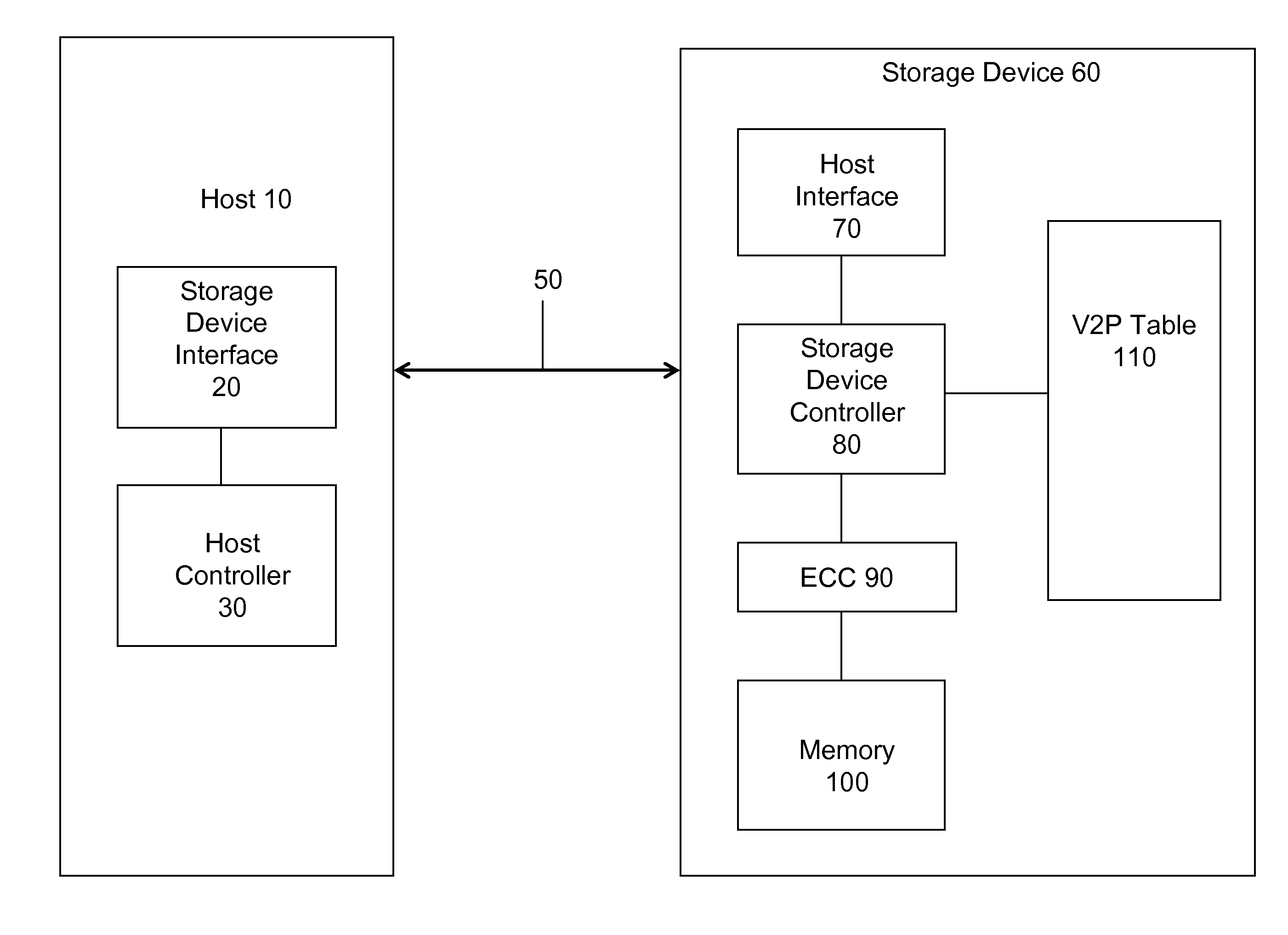
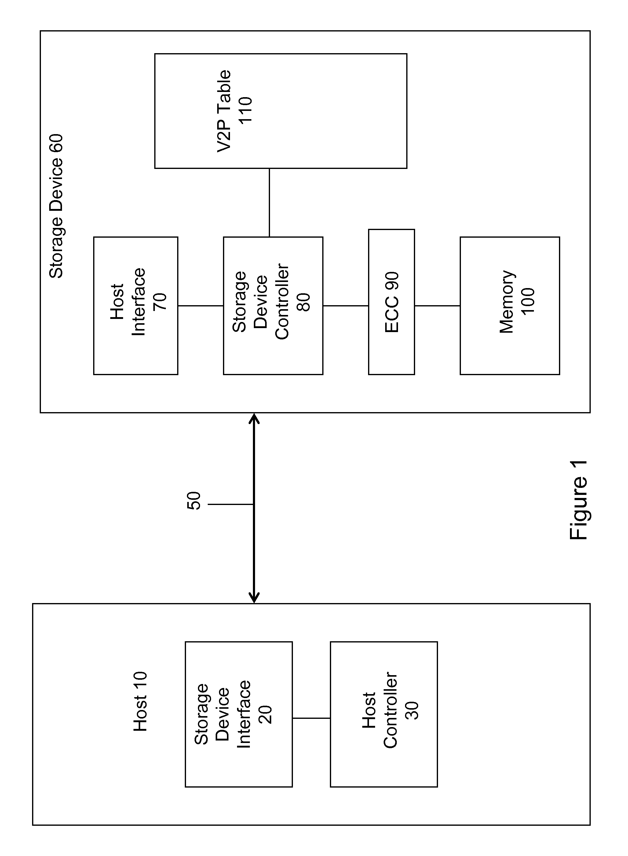
[0041]Turning now to the drawings, FIG. 1 is a block diagram of a host in communication with a memory device of an embodiment via a communication bus. FIG. 1 includes a number of computing technologies such as a host 10, a storage device interface 20, a host controller 30, a storage device 60, a host interface 70, a storage device controller 80, a V2P table 110, an ECC block 90, a...


PUM


Abstract

Techniques for optimizing data movement in electronic storage devices are disclosed. In one particular exemplary embodiment, the techniques may be realized as a method for optimizing data movement in electronic storage devices comprising maintaining, on the electronic storage device, a data structure associating virtual memory addresses with physical memory addresses. Information can be provided regarding the data structure to a host which is in communication with the electronic storage device. Commands can be received from the host to modify the data structure on the electronic storage device, and the data structure can be modified in response to the received command.

Description

CROSS-REFERENCE TO RELATED APPLICATIONS[0001]This application claims priority to U.S. Provisional Application No. 61 / 510,319, filed Jul. 21, 2011, the entire disclosure of which is incorporated by reference herein in its entirety.BACKGROUND[0002]Memory devices are often used to store data provided by a host. In many situations, the host needs to reorganize previously-stored data from one location in the memory device to another location in the memory device. This reorganization may include move or copy operations, which may be used, for example, when the host is defragmenting the memory device.[0003]A pointer is a programming data type whose value refers directly to (“points to”) another value stored elsewhere in a computer memory using the value's memory address. A pointer references a location in memory, so the value of a pointer is the memory address of the underlying data, and not the data itself. Obtaining the underlying data at the memory address to which a pointer refers is k...

Claims


Application Information

Patent Timeline
IPC IPC(8): G06F12/08
CPCG06F12/0246G06F2212/7201G06F2212/7205G06F3/0676G06F3/0611G06F3/0665G06F3/0608
Inventor GIVARGIS, TONY DIGALEHSADRI, REZA
Owner WESTERN DIGITAL TECH INC
Learn More