Waste heat regeneration system

a technology of waste heat and regeneration system, which is applied in the direction of steam engine plants, mechanical equipment, machines/engines, etc., can solve the problems of cavitation in the pump, and achieve the effect of preventing the degree of supercooling from becoming excessiv

Inactive Publication Date: 2013-01-31
TOYOTA IND CORP
View PDF7 Cites 8 Cited by
  • Summary
  • Abstract
  • Description
  • Claims
  • Application Information

AI Technical Summary

Benefits of technology

[0009]According to the waste heat regeneration system of the present invention

Problems solved by technology

When an abrupt change in the temperature occurs in the external air as the cooling medium, the liquid operating fluid

Method used


Image

  • Waste heat regeneration system
  • Waste heat regeneration system

Examples


embodiment

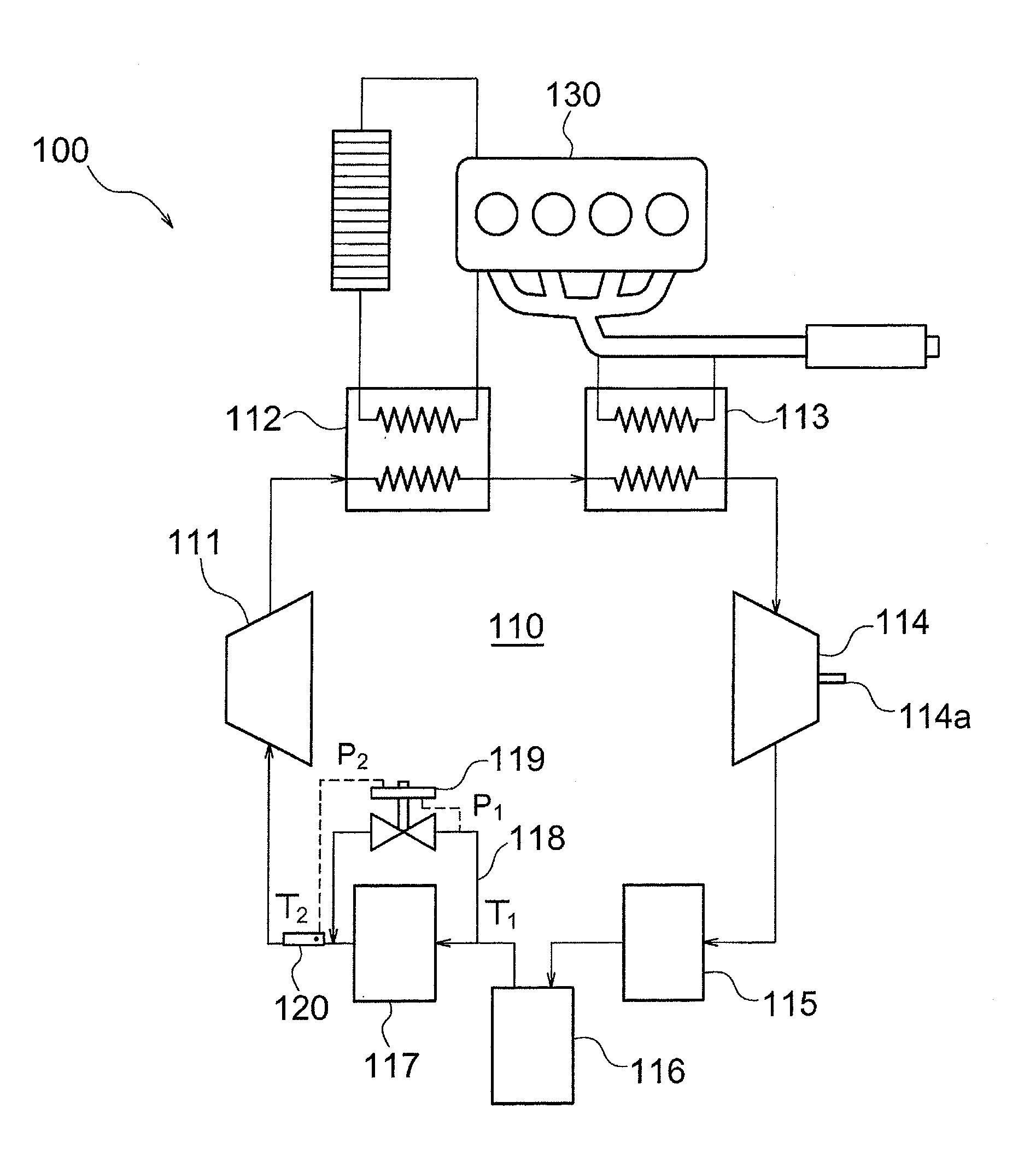
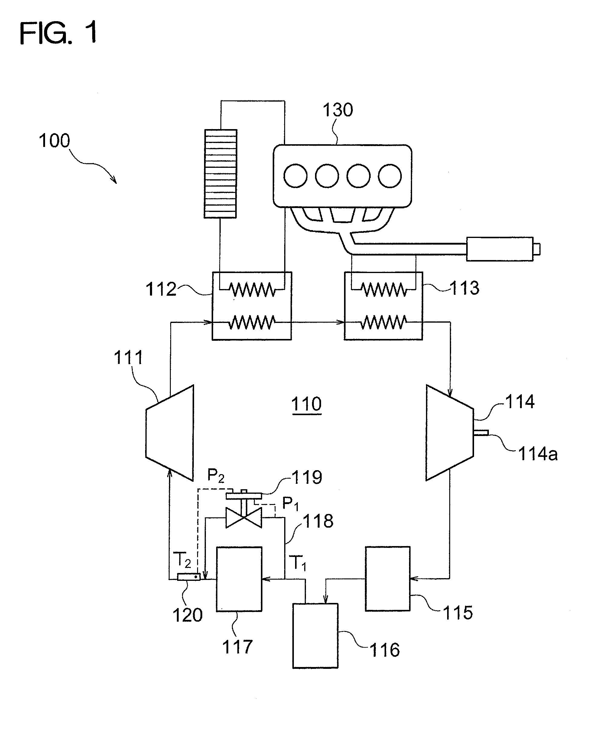
[0012]A configuration of a waste heat regeneration system 100 according to the embodiment of the present invention is illustrated in FIG. 1.

[0013]The waste heat regeneration system 100 includes a pump 111, a coolant boiler 112, an exhaust gas boiler 113, an expander 114, a condenser 115, a gas-liquid separator 116, and a supercooler 117, and these components are sequentially and circularly connected to each other so as to form a closed circuit 110.

[0014]The pump 111 pressure-feeds an operating fluid into the closed circuit 110. The coolant boiler 112 is a first heat exchanger, and heats the operating fluid through the heat exchange with the coolant of an engine 130. The exhaust gas boiler 113 is a second heat exchanger, and heats the operating fluid through the heat exchange with exhaust gas discharged from the engine 130. The expander 114 recovers mechanical energy (power) by expanding the operating fluid which was heated and evaporated in the coolant boiler 112 and the exhaust gas...


PUM


Abstract

A waste heat regeneration system includes a pump, a coolant boiler, an exhaust gas boiler, an expander, a condenser, a gas-liquid separator and a supercooler. A flow control valve maintains a temperature difference (T1-T2) at a predetermined value or less by adjusting the amount of an operating fluid which flows in a bypass flow path through the control of an opening degree based on a pressure difference (P1-P2) corresponding to the temperature difference (T1-T2) between the temperature (T1) of the operating fluid on the upstream side of the supercooler and the temperature (T2) of the operating fluid on the downstream side thereof. Accordingly, the degree of supercooling is prevented from becoming excessive and the waste heat regeneration efficiency of a Rankine cycle device can be maintained.

Description

TECHNICAL FIELD[0001]The present invention relates to a waste heat regeneration system, and particularly, to a waste heat regeneration system that uses a Rankine cycle device.BACKGROUND ART[0002]A waste heat regeneration system which uses a Rankine cycle device recovering mechanical energy (power) from waste heat of a vehicle engine has been developed. A typical Rankine cycle device includes a pump which pressure-feeds an operating fluid, a heat exchanger which heats the operating fluid through the heat exchange with the waste heat of an engine, an expander which recovers mechanical energy by expanding the heated operating fluid, and a condenser which cools and condenses the expanded operating fluid, and these components are sequentially and circularly connected to each other so as to form a closed circuit.[0003]In the waste heat regeneration system mounted on a vehicle, external air of the vehicle is used as a cooling medium for the condenser in many cases. When an abrupt change in...

Claims


Application Information

Patent Timeline
IPC IPC(8): F01N5/02F01K23/06F01K9/00F02G5/02
CPCF01K23/065F01N5/02F01N2240/02F01K23/10F02G2260/00Y02T10/16Y02T10/166F02G5/04Y02T10/12
Inventor ENOKIJIMA, FUMINOBUIGUCHI, MASAOMORI, HIDEFUMI
Owner TOYOTA IND CORP
Why Eureka
Try Eureka