Apparatus and method for desulfation of a catalyst used in a lean burn methane source fueled combustion system

a technology of methane source and desulfurization method, which is applied in the direction of physical/chemical process catalysts, exhaust treatment, electric control, etc., can solve the problems of high unfavorable, achieve the effect of enhancing the performance of the catalyst, facilitating the desulfation of the catalyst, and enhancing the operation of the catalys

Inactive Publication Date: 2019-01-22
UMICORE AG & CO KG
View PDF40 Cites 7 Cited by
  • Summary
  • Abstract
  • Description
  • Claims
  • Application Information

AI Technical Summary

Benefits of technology

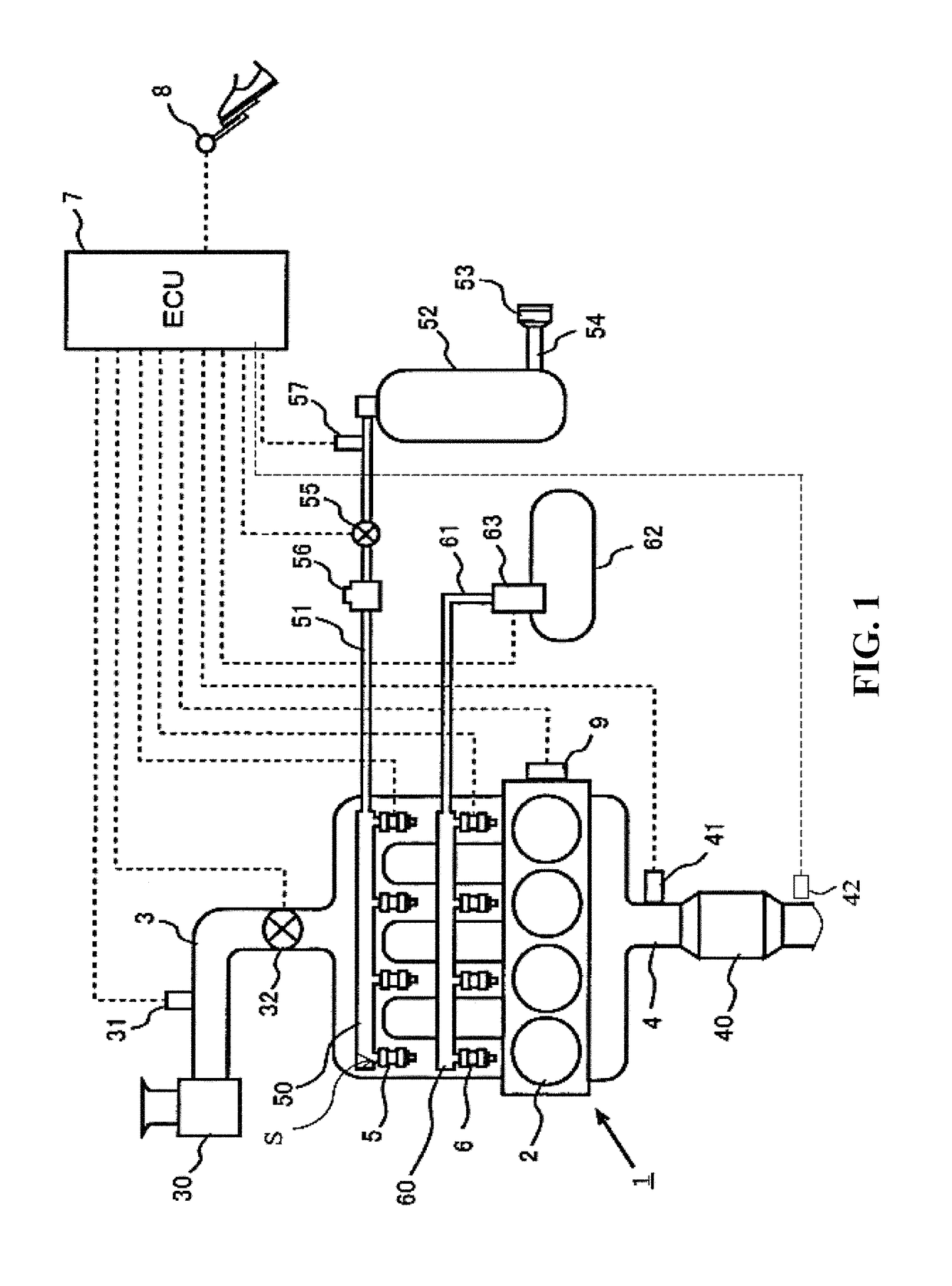
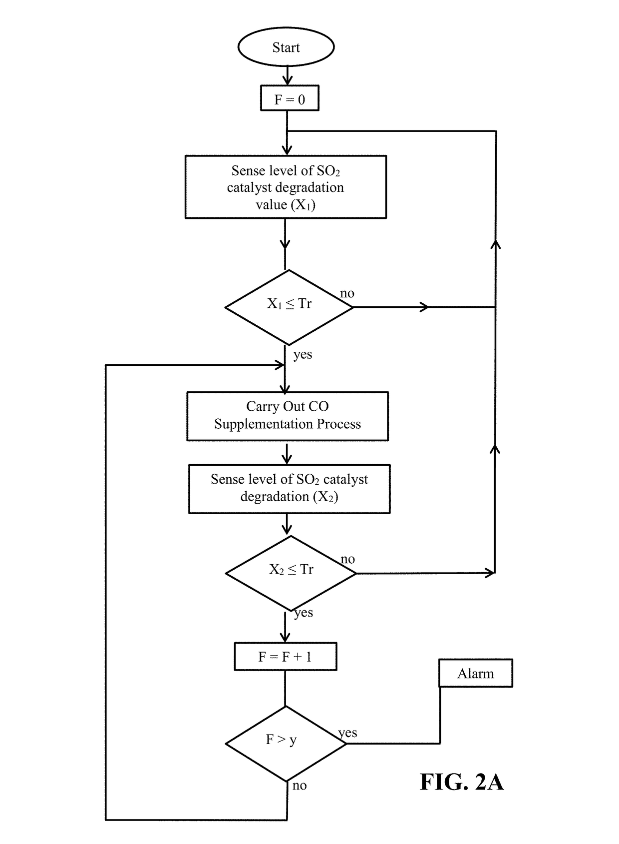
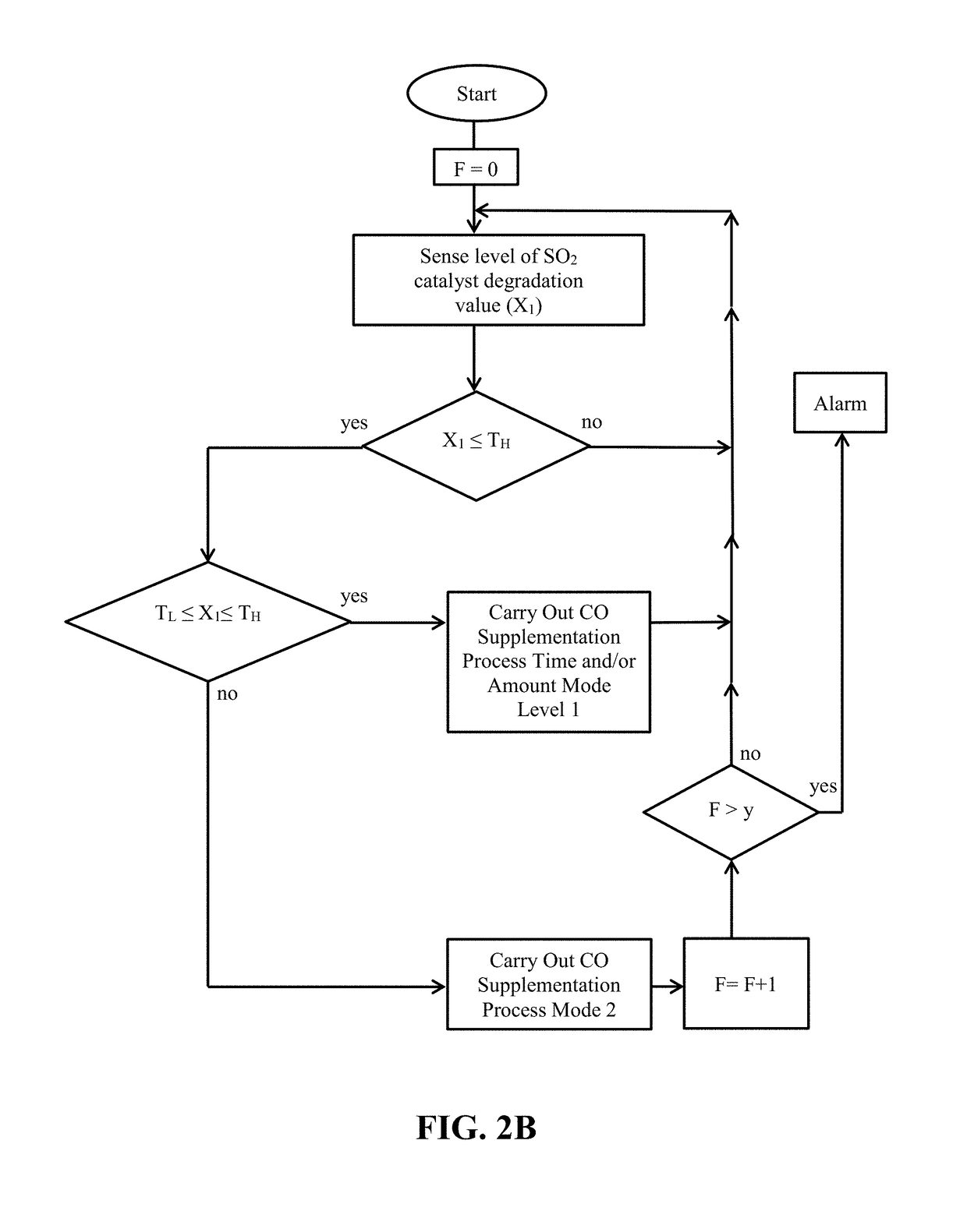
[0023]As noted, the present invention takes into consideration that methane is harder to burn as compared to CO. For instance, depending on catalyst formulations and testing conditions, CO light-off temperatures can be 200° C. lower than that of methane. By introducing more CO to the exhaust under the present invention, the exotherm generated by CO oxidation can more readily achieve a local thermal treatment effect on a sulfur degraded lean burn methane source fueled (e.g., NG) combustion device (e.g., a vehicle engine) catalyst so as to facilitate a reversal in sulfur poisoning of that catalyst. Thus, a technique featured under the present invention is one that effectively provides an in-situ desulfation / regeneration using the heat from CO oxidation. A second feature of the high and very rapid oxidation of CO over, for example, a Pd CNG catalyst is that the “local” temperature at the Pd crystallites will be very high while at the same time the “local gas composition” may be close to stoichiometry or slightly rich due to the very rapid consumption of oxygen at those localized regions, coupled with limitations in the rate of diffusion of oxygen to the Pd crystallites. Thus the presence of CO coupled with a very high combustion rate can essentially achieve the same effect as that of making the overall exhaust rich as by EMS adjustment, which is highly unfavorable. In other words, the presence of high levels of CO, with its associated fast removal of local environment oxygen under the present invention, can essentially achieve the same effect as that of making the overall exhaust rich, from the perspective of the local environment where catalysis is occurring, i.e. at the Pd / PdO crystallites, The present invention, with its overall lean environment relative to the catalyst, also avoids the degree of hydrogen sulfide generation that can occur under an overall rich atmosphere such as that generated periodically in the prior art rich-lean toggling. The present invention also features a system wherein the added CO in the exhaust provides for a lessening of the impact of water vapor in the exhaust in that CO conversion is less inhibited by the presence of water vapor as compared to methane.
[0043]The present invention is also inclusive of a method of enhancing a catalyst performance in a lean burn (methane fuel sourced) combustion device (e.g., engine) exhaust passageway, that includes supplementing the CO content of the lean burn engine exhaust so as to reactivate the catalyst (e.g., reactivate the catalyst by removal of sulfur build up on that catalyst) while retaining an overall lean lambda state in the exhaust reaching the catalyst during CO supplementation. For example, in an embodiment of the invention there is featured a lean burn combustion device (e.g., engine) oxidation catalyst with Pd as the, or one of the, active PGM materials, which catalyst is operating in the exhaust passageway of the (e.g., CNG) lean burn combustion device (e.g., engine) and is reactivated by adding, in a controlled fashion, to the CO content of the exhaust, which facilitates the desulfation of that catalyst.

Problems solved by technology

Thus the presence of CO coupled with a very high combustion rate can essentially achieve the same effect as that of making the overall exhaust rich as by EMS adjustment, which is highly unfavorable.

Method used


Image

  • Apparatus and method for desulfation of a catalyst used in a lean burn methane source fueled combustion system
  • Apparatus and method for desulfation of a catalyst used in a lean burn methane source fueled combustion system
  • Apparatus and method for desulfation of a catalyst used in a lean burn methane source fueled combustion system

Examples


examples

[0094]To illustrate the improved performance of the present invention through use of the present invention's CO supplementation apparatus and method used fur the purpose of desulfation of catalysts subject to exhaust gas contamination, some examples and comparisons are described below.

Testing Equipment Set Up

[0095]FIG. 3 shows a schematic illustration of test equipment suited for use in analyzing samples representing the present invention and comparative examples. That is, FIG. 3 shows a schematic illustration of CNG engine simulation test equipment set up for comparative and present invention analysis. As shown in FIG. 3 there is provided a variety of different gas sources that are flow controlled via mass flow controllers or MFC's. The MFC's provide gas blending to obtain the desired flow volume percentages travelling through the test system and can be used to block off any flow, which facilitates making the gas blend comparisons described below.

[0096]As further shown in FIG. 3, t...


PUM

PropertyMeasurementUnit
pressureaaaaaaaaaa
temperatureaaaaaaaaaa

Abstract

Apparatus for reactivating a sulfur poisoned oxidation catalyst operating in exhaust of a lean burn, methane source fueled combustion device. Reactivation includes desulfation of the poisoned catalyst through a CO supplementation apparatus communicating with the control unit that is adapted to supplement CO content in exhaust reaching the catalyst, while avoiding an overall rich exhaust atmosphere at the catalyst (e.g., an added supply of hydrocarbons to one or more-of the lean burn engine's combustion chambers as by an ECU controlled extra supply of NG to some of the combustion chambers). Also featured is a method for desulfation of an oxidation catalyst of a lean burn CNG engine by supplying excess CO to exhaust reaching the catalyst while retaining an overall lean state, and a method of assembling an apparatus for reactivating a sulfur deactivated lean burn NG engine catalyst by assembling a CO supplementation apparatus with control unit.

Description

FIELD OF THE INVENTION[0001]This invention relates to the technology of catalytically converting emissions from a lean burn combustion device that is a methane source fueled device. Examples of lean burn methane source fueled combustion devices include stationary combustion units such as those used in natural gas supplied power plants and methane source fueled engines such as a natural gas fueled engine. An example of a natural gas fueled engine includes a compressed natural gas (CNG) fueled engine, and the invention is inclusive of an apparatus and a method for catalytic conversion of exhaust gases containing saturated hydrocarbons such as methane that are found in the exhaust of such combustion devices. The present invention is further inclusive of an apparatus and method directed at avoiding sulfur degradation or deactivation of a catalyst used in the emission control of the lean burn methane source fueled combustion device (e.g., an engine such as a CNG engine) through a control...

Claims


Application Information

Patent Timeline
Patent Type & Authority Patents(United States)
IPC IPC(8): F01N3/08F01N3/36F01N3/10B01D53/94B01D53/96F02B43/10B01J38/04F01N3/20F01N11/00F01N9/00
CPCF01N3/206B01D53/9495B01D53/96B01J38/04F01N3/0885F01N3/101F01N3/103F01N3/2033F01N3/36F01N9/00F01N11/00F02B43/10B01D53/944F02B2043/103B01D2251/204B01D2255/1023F01N2260/04F01N2450/40F01N2550/02F01N2570/04F01N2570/20F01N2590/08F01N2590/10F01N2610/03F01N2610/05F01N2610/06Y02C20/20Y02T10/12Y02T10/40Y02A50/20B01D53/9454B01D2255/1021B01J23/44B01J23/96F01N3/2825F01N2370/02F01N2610/146F01N2900/1612F02D41/027F02M21/0209F02M21/0215
Inventor HAN, XUENUNAN, JOHN
Owner UMICORE AG & CO KG
Why Eureka
Try Eureka