Lubrication structure for bearing section

a technology for internal combustion engines and lubrication structures, which is applied in the direction of auxiliaries, machines/engines, crankshafts, etc., can solve the problems of increasing the number of parts and complicated structures, and achieve the effects of reducing the number of parts, and enhancing the rigidity around the oil receiving section

Active Publication Date: 2013-01-31
HONDA MOTOR CO LTD
View PDF3 Cites 8 Cited by
  • Summary
  • Abstract
  • Description
  • Claims
  • Application Information

AI Technical Summary

Benefits of technology

[0018]In accordance with another aspect of the invention, the bearing restriction member serves also as a bearing restriction member for a second bearing for a second rotational shaft positioned adjacent the rotational shaft. Therefore, the bearing restriction member can be utilized as the bearing restriction member for the second bearing of the second rotational shaft without providing a bearing restriction member separately for both of the bearings, and reduction of the number of parts can be achieved.
[0019]In accordance with another aspect of the invention, the bearing restriction member is configured so as to extend to a shaft end portion of a further shaft supported by the wall portion and contact with the shaft end portion. Thus, the bearing restriction member can be used as a coming off preventing device and to retain or hold the further shaft, and a reduction of the number of parts can be achieved.
[0020]Based upon another aspect of the invention, a boss portion of a fastening device for attaching the bearing restriction member to the oil receiving portion is formed integrally with the oil receiving portion on the wall portion. Since the boss portion of the fastening device is integrated, rigidity around the oil receiving section is enhanced.
[0021]In accordance with another aspect of the invention, a boss portion of a fastening device for attaching the bearing restriction membe...

Problems solved by technology

However, if it is intended to specially provide an oil supply device, then there is ...

Method used


Image

  • Lubrication structure for bearing section
  • Lubrication structure for bearing section
  • Lubrication structure for bearing section

Examples


Embodiment Construction

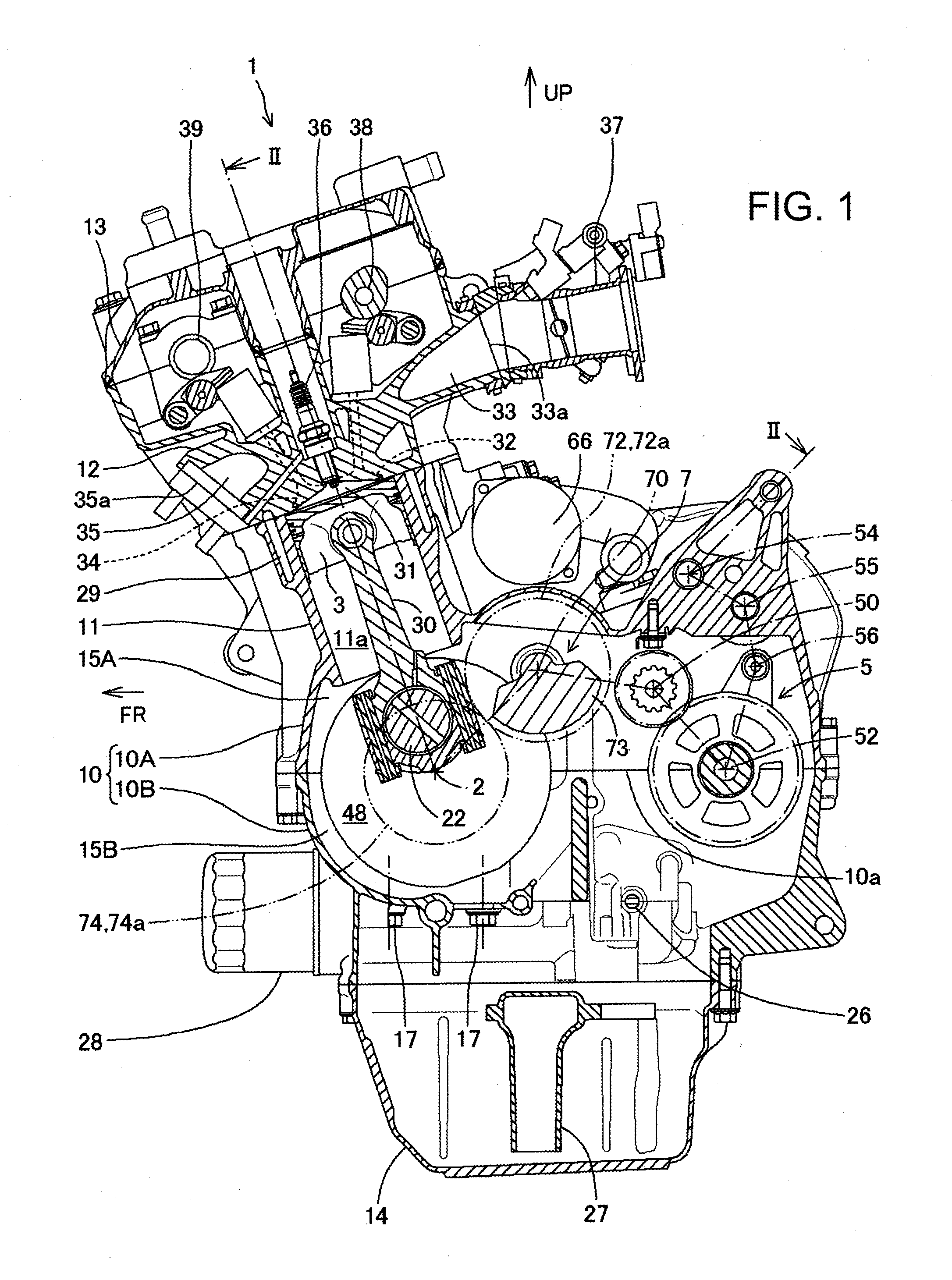
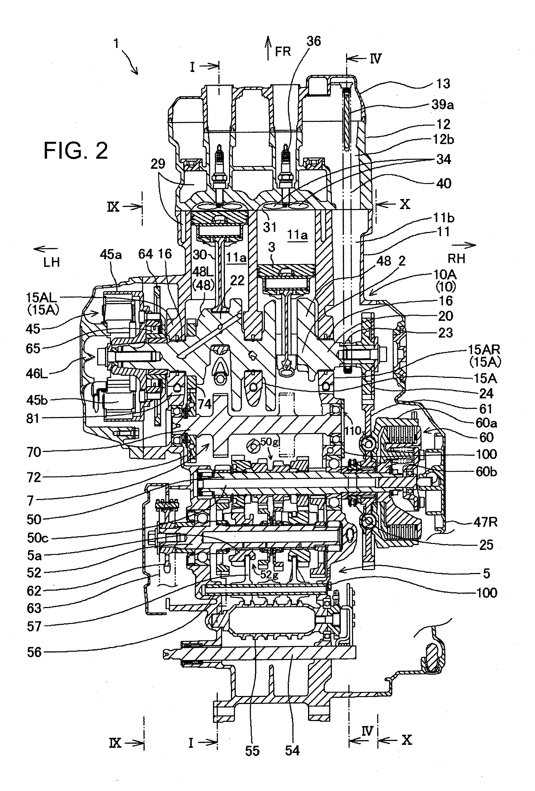
[0035]A lubrication structure for a bearing section of an internal combustion engine of an embodiment according to the present invention is described with reference to FIGS. 1 to 12.

[0036]It is to be noted that such directions as forward, rearward, leftward, rightward, upward and downward directions in the description of the present specification and the claims are represented with reference to the direction of a small size vehicle in a state in which the internal combustion engine with a balancer for a motorcycle according to the present embodiment is mounted on the vehicle.

[0037]Further, in the figures, an arrow mark FR denotes a forward direction of the vehicle, LH a leftward direction of the vehicle, RH a rightward direction of the vehicle, and UP an upward direction of the vehicle.

[0038]FIGS. 1 to 12 relate to an embodiment of the present invention, and in FIG. 1, an internal combustion engine with a balancer (hereinafter referred to as internal combustion engine 1) is shown in...


PUM


Abstract

A lubrication structure for a bearing section of an internal combustion engine including a crankcase having a wall portion, a bearing secured to the wall portion, a rotational shaft supported for rotation by the bearing, and a bearing restriction member disposed on a side face of an outer race portion of the bearing and configured to suppress coming off of the bearing, wherein an oil receiving portion formed in a swollen state on the wall portion along an outer periphery on the outer side of an outer periphery below the center axis of the bearing, and an oil reserve section is provided so as to extend over the oil receiving portion and the bearing restriction member.

Description

BACKGROUND OF THE INVENTION[0001]1. Field of the Invention[0002]The present invention generally relates to a lubrication structure for a bearing section of an internal combustion engine and, more particularly, to a lubrication structure for a bearing section using a simple oil supplying device.[0003]2. Description of Related Art[0004]An internal combustion engine for a motorcycle wherein a breather plate, which configures a breather by being attached to an inner wall of a crankcase on the speed change gear accommodation side, is utilized such that a retainer section (bearing restriction section) for preventing a bearing from coming off, which bearing supporting a countershaft of a speed change gear, is provided at a portion of the breather plate. Such a internal combustion engine structure is disclosed in Japanese Patent No. 3060628.[0005]In the internal combustion engine disclosed in Japanese Patent No. 3060628, a lower portion of the crankcase serves as an oil reserve chamber, and...

Claims


Application Information

Patent Timeline
IPC IPC(8): F01M7/00
CPCF01M2011/028F01M5/025
Inventor NAGAHASHI, YOSHIKITAJIRI, KAZUYAOKUBO, FUMIAKI
Owner HONDA MOTOR CO LTD
Why Eureka
Try Eureka