
Door machine of fireproof door

a door machine and fireproof door technology, applied in the direction of mechanical devices, door/window protective devices, wing accessories, etc., can solve the problems of complex structure and huge volume of the failsafe door machine of fireproof door, and achieve the effect of improving the disadvantages of complicated structure, huge volume and inconvenient operation in the prior ar

Active Publication Date: 2013-01-31
HSIEH CHUNG HSIEN
View PDF4 Cites 5 Cited by
  • Summary
  • Abstract
  • Description
  • Claims
  • Application Information

AI Technical Summary

Benefits of technology

The present invention provides a simplified door machine for fireproof rolling doors. This reduces the complexity, size, and inconvenience of prior art. The machine uses a torsion spring with inner and outer ends, and a clutch mechanism to control the rotation of the input axle. The machine can be activated or deactivated automatically based on the state of the machine. The mechanisms for the structure of the machine are modulized and arranged one above another, making the structure compact. The machine can be configured as a failsafe type or a non-failsafe type, with the two versions sharing common parts and reducing development and production costs. The invention also includes an exciting circuit for clutch which maintains power for the electromagnetic clutch under normal power supply conditions. This circuit includes a delay circuit formed by a plurality of capacitors which charged in the normal state. The electromagnetic clutch can be energized and temporarily excited by the capacitors immediately after the abnormal power interruption caused by the fire accident so that the timing for shutting the door can be delayed for personnel evacuation.

Problems solved by technology

The structure of this failsafe door machine of fireproof door is very complicated and has a huge volume.

Method used


Image

  • Door machine of fireproof door
  • Door machine of fireproof door
  • Door machine of fireproof door

Examples


first embodiment

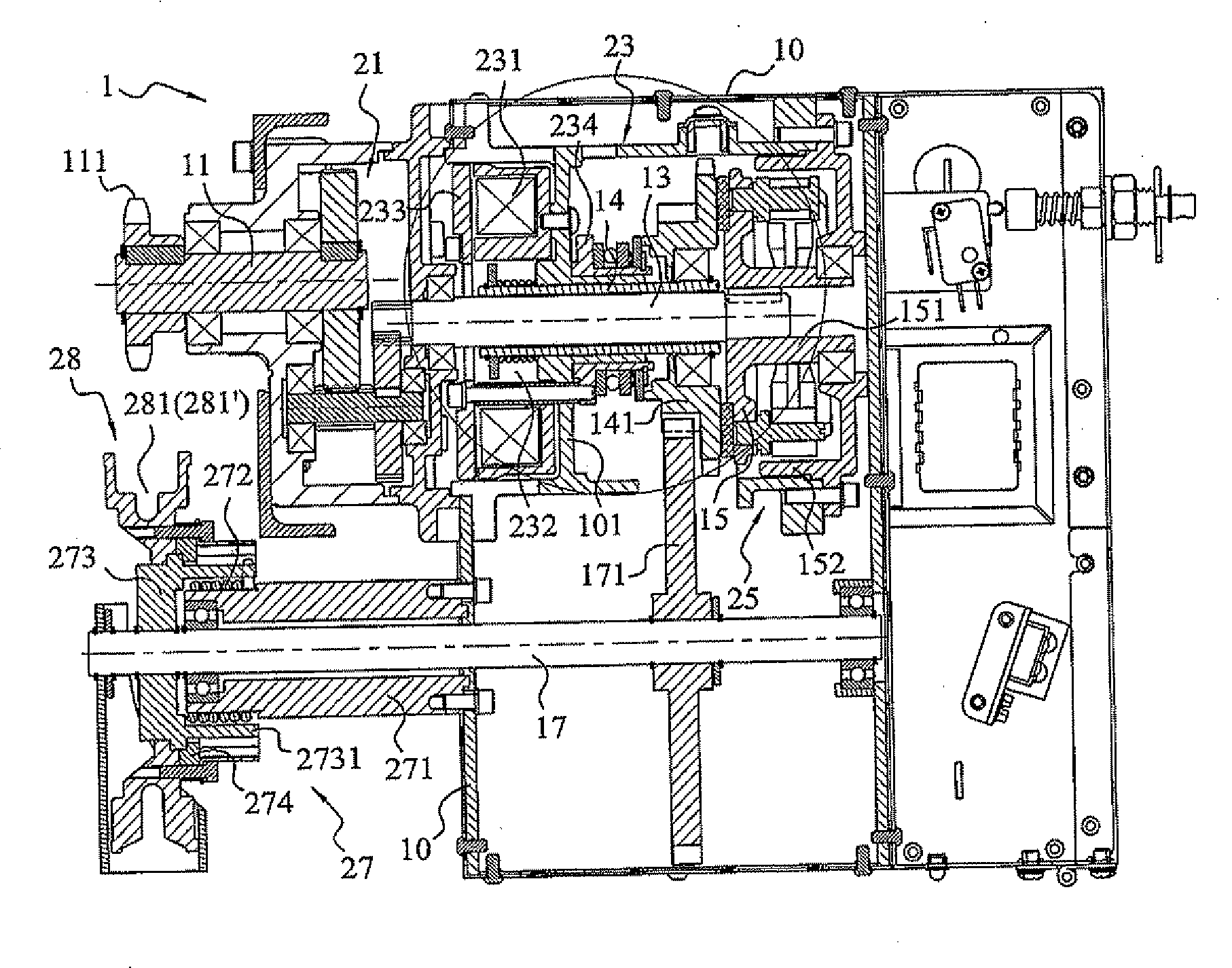
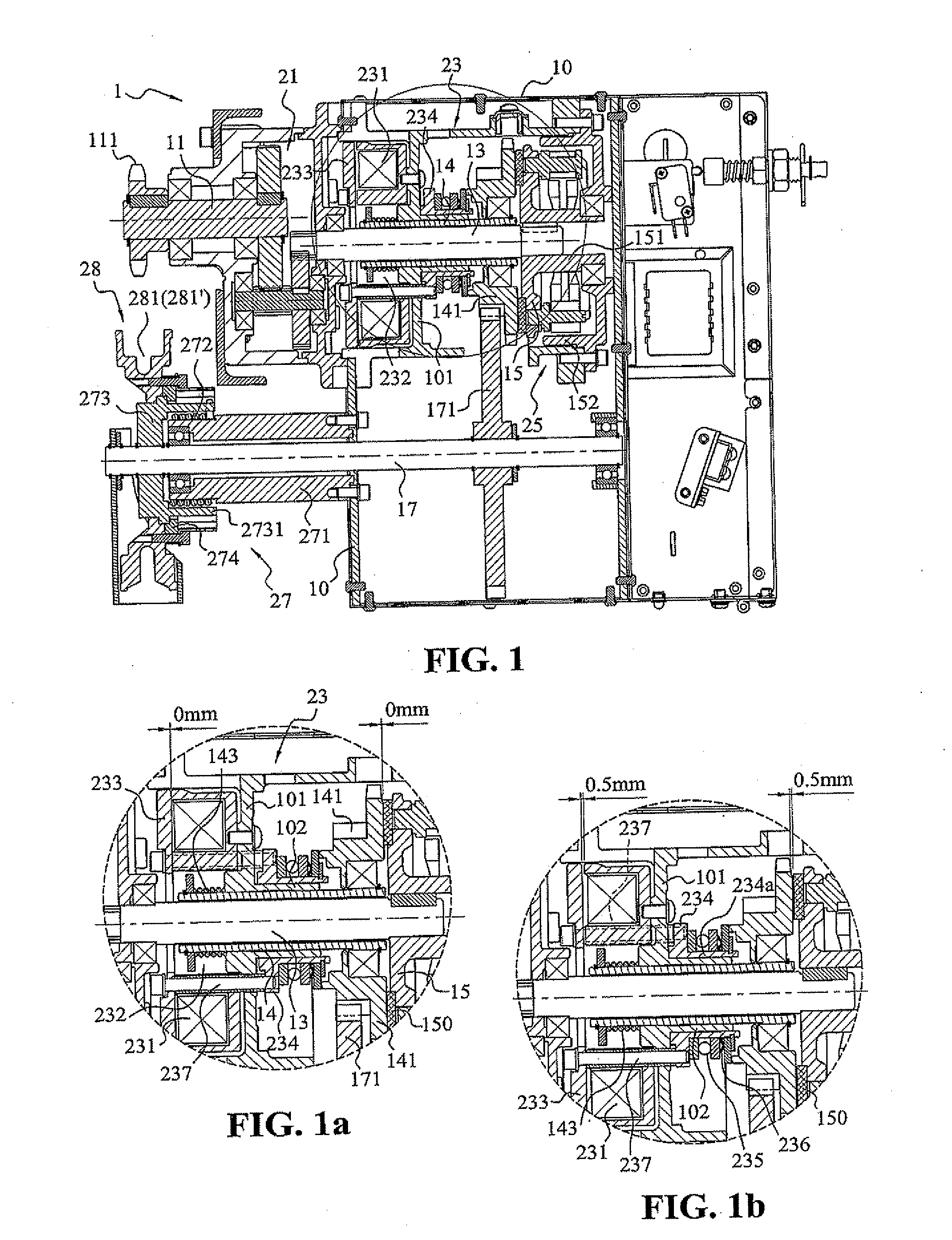
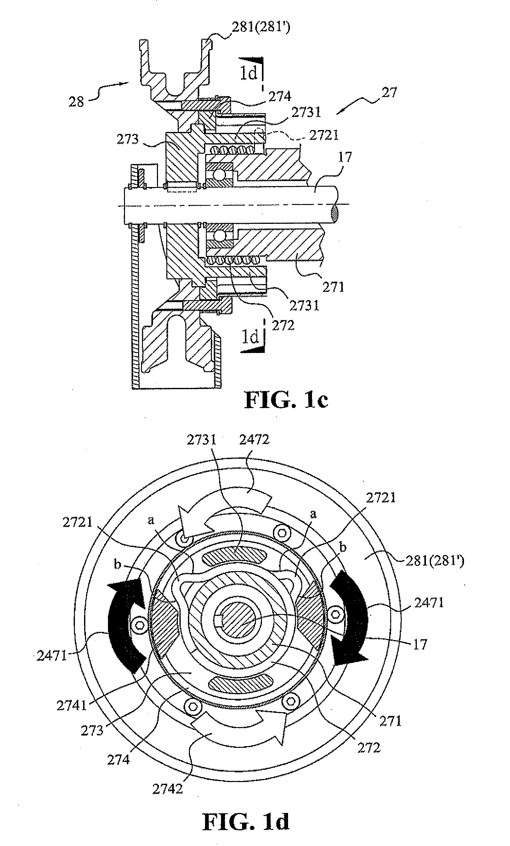
[0015]Firstly, the failsafe type door machine of fireproof door of the present invention is described by referring to FIG. 1 and FIGS. 1a to 1h. As shown in FIG. 1, the door machine 1 of the present invention comprises:

[0016]a housing 10 enclosing an accommodation space and having an output axle 11 pivotally disposed at a first set position of the housing 10, the output axle 11 having an output wheel 111 fixed at the left end thereof for rotating a reel (not shown) of the door panels; an input axle 17 pivotally disposed at a second set position of the housing 10, the input axle 17 being rotated by applying an external force to an input wheel 281 fixed to the left end of the input axle 17;

[0017]a central axle 13 pivotally disposed at a third set position of the housing 10, the left end of the central axle 13 having a conventional transmission means such as gears fixed to the left end of the central axle 13 so as to be linked with the output axle 11, and an end disc 15 fixed to the ri...

second embodiment

[0043]FIG. 2 is a schematic sectional view showing the failsafe type door machine of fireproof door of the present invention.

[0044]FIG. 2a is a partial perspective view showing the driving mechanism of FIG. 2.

third embodiment

[0045]FIG. 3 is a schematic sectional view showing the non-failsafe type door machine of fireproof door of the present invention.

[0046]FIG. 3a is a partially enlarged view of the embodiment in FIG. 3, showing that the clutch mechanism is in engaged state.

[0047]FIG. 3b is a partially enlarged view of the embodiment in FIG. 3, showing that the clutch mechanism is in released state.


PUM


Abstract

A door machine of a fireproof door comprises an input end to be actuated by an input axle; an output end loaded with weight of door panels, the loading force of which is transmitted back to a central axle through an output axle; a clutch mechanism normally connecting the central axle with the input axle together; a brake mechanism including a torsion spring which is integrated with the input axle of the input end and one end of which bears the loading force came from the central axle to shrink the inner diameter thereof so that the input axle is in an immobilized state; when an external force is applied to the input end, the other end of the torsion spring resisting against the weight of the door panels to expand the inner diameter thereof so that the input axle is rotated.

Description

BACKGROUND OF INVENTION[0001]1. Field of the Invention[0002]The present invention relates to a door machine of a rolling door, more particularly to a door machine of a fireproof door which can be shut by rolling-down of door panels due to its own weight in the event of a fire accident.[0003]2. Brief Description of the Prior Art[0004]General door machine used in a fireproof rolling door comprises either a failsafe type or a non-failsafe type door machine according to the type of operation. In power interruption condition, the failsafe type door machine is releases a brake so as to close the fireproof door at once regardless of the cause of power interruption. In other words, even in the case that the power is not interrupted in the event of a fire accident, the power source can be cut off to release the brake by a fire fighting control device such as a smoke detector, a temperature sensor or the other fire monitoring device so that the door panels are rolled down due to their own wei...

Claims


Application Information

Patent Timeline
IPC IPC(8): E06B9/80E06B9/56
CPCE06B5/16A62C2/241E06B9/74E05F15/72E05Y2201/502E05Y2900/134E06B9/84E05Y2900/106E05Y2900/00
Inventor HSIEH, CHUNG HSIEN
Owner HSIEH CHUNG HSIEN
Learn More