Hammer

a hammer and drill bit technology, applied in the field of hammer drills, can solve the problems of design problems, damage to the support structure of the beat piece and/or the tool holder,

Active Publication Date: 2013-01-31
BLACK & DECKER INC
View PDF10 Cites 15 Cited by
  • Summary
  • Abstract
  • Description
  • Claims
  • Application Information

AI Technical Summary

Benefits of technology

[0027]It is the object of the present invention to provide a design of beat piece and beat piece suppor

Problems solved by technology

However, it desirable to stop the ram from continuing to repetitively strike the beat piece as it will result in damaging the support structure for the

Method used


Image

  • Hammer
  • Hammer
  • Hammer

Examples


first embodiment

[0054]the present invention will now be described with reference to FIG. 6.

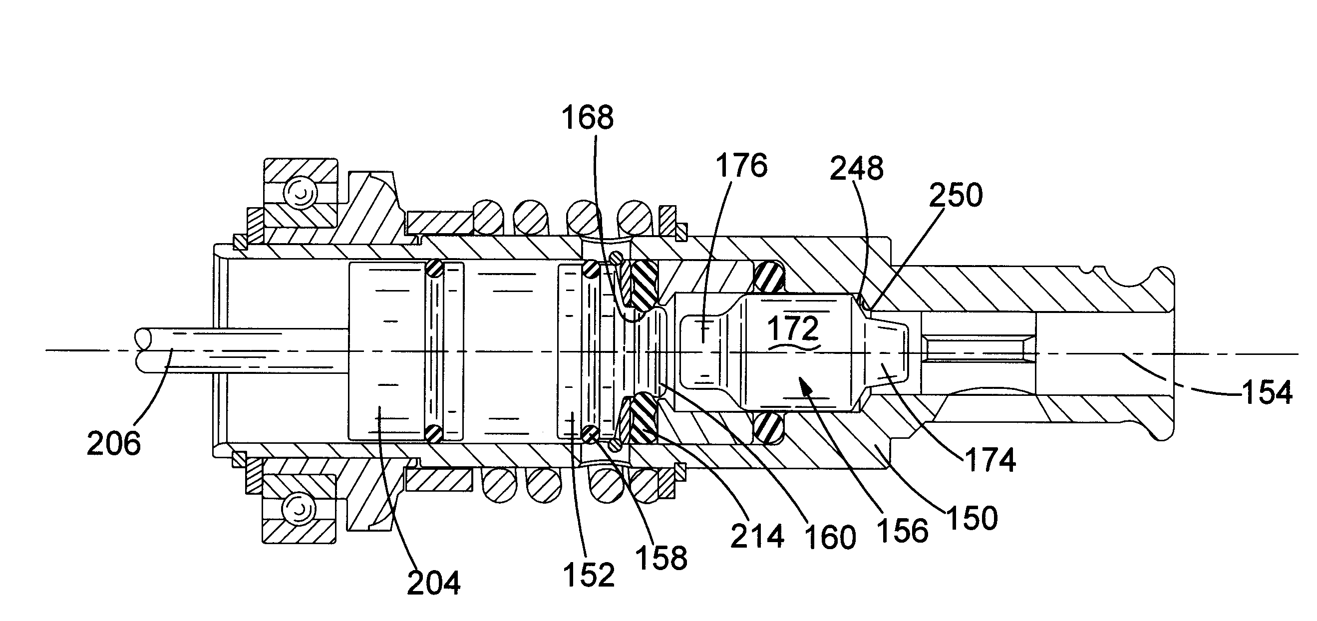
[0055]FIG. 6 shows the new design of beat piece 156 in accordance with the present invention. Where the same features in the first embodiment are shown in the prior art example described above, the same reference numbers are used. The only difference between the prior art design and the first embodiment is the design of the beat piece only.

[0056]The rear section 176, first angled region 242 and middle section 172 of the beat piece 156 are the same as the prior art design and are circular in cross section in any plane which extends perpendicularly to the longitudinal axis 154 of the beat piece, the centre of each circular cross section being the longitudinal axis 154 of the beat piece 156.

[0057]However, the design of front section 174 and second angled region 248 has changed.

[0058]The front section 174 and second angled region 248 are both still frusto conical in shape and circular in cross section in any plan...

second embodiment

[0061]the present invention will now be described with reference to FIG. 7.

[0062]FIG. 7 shows the new design of spindle 150 in accordance with the present invention. Where the same features in the prior art description described previously are present in the second embodiment, the same reference numbers are used. The only difference between the prior art design and the second embodiment is the design of the spindle only.

[0063]As with the prior art design, the second angled shoulder 250 formed on the inner wall of the spindle 150 is circular in cross section in any plane which extends perpendicularly from the longitudinal axis 154 of the spindle 150. However, the centre of the circular cross sections is not located on the longitudinal axis 154 but on a third axis 400 which runs parallel to the longitudinal axis 154 but is located in close proximity to the longitudinal axis. This results in the second angled shoulder 250 being eccentric relative to the longitudinal axis 154 of the spi...


PUM

PropertyMeasurementUnit
Proximity effectaaaaaaaaaa

Abstract

A hammer mechanism including: a motor; a piston reciprocatingly driven by the motor; a ram reciprocatingly driven by the reciprocating piston via an air spring; a beat piece supported in an axially slideable manner within a beat piece support structure which, during the normal operation of the hammer mechanism, is repetitively struck by the ram and which transfers the impacts to a cutting tool when held by the tool holder; wherein the beat piece comprises a first impact surface and the beat piece support structure including a second impact surface, the first and second impact surfaces coming into contact with each other when the beat piece axially slides to its furthest position away from the ram; and wherein the shape of the two surfaces relative to each other is arranged so that there is a non-uniform amount of contact between the first and second surfaces around the longitudinal axis.

Description

CROSS-REFERENCE TO RELATED APPLICATIONS[0001]This application claims priority, under 35 U.S.C. §119(a)-(d), to UK Patent Application No. GB 11 128 29.5 filed Jul. 26, 2011, the contents of which are incorporated herein by reference in its entirety.FIELD OF THE INVENTION[0002]The present invention relates to a hammer drill, and in particular, to a hammer drill having a ram which is capable of repetitively striking a cutting tool via a beat piece.BACKGROUND OF THE INVENTION[0003]A typical hammer drill comprises a body in which is mounted an electric motor and a hammer mechanism. A tool holder is mounted on the front of the body which holds a cutting tool, such as a drill bit or a chisel. The hammer mechanism typically comprises a ram, slideably mounted in a cylinder, reciprocatingly driven by a piston via an air spring, the piston being reciprocatingly driven by the motor via a set of gears and a crank mechanism or wobble bearing. The ram in turn repeatedly strikes the end of the cutt...

Claims


Application Information

Patent Timeline
IPC IPC(8): B25D17/06
CPCB25D17/06B25D2250/245B25D2217/0015
Inventor FRIEDRICH, ANDREAS
Owner BLACK & DECKER INC
Why Eureka
Try Eureka