Floating disc brake, method of assembling same, and assemblies consisting of pad clips and return springs

a technology of floating disc brake and assembly method, which is applied in the direction of brake systems, mechanical equipment, transportation and packaging, etc., can solve the problems of troublesome assembly operation, increased assembling cost, and inability to support the return spring, so as to improve the handling property improve the mounting operability of the pad clip, and make the pad clip (clip elements) smaller/lighter

Active Publication Date: 2013-01-31
AKEBONO BRAKE IND CO LTD
View PDF3 Cites 33 Cited by
  • Summary
  • Abstract
  • Description
  • Claims
  • Application Information

AI Technical Summary

Benefits of technology

[0063]According to the above configuration, it is possible to make the pad clip (clip elements) smaller / lighter, compared to a configuration where the entire pad clip is integrally formed (for example, a portal in which a pair of leg sections is connected by a connection section). Therefore, it is possible to improve the handling property of the pad clip, thereby improving the mounting operability of the pad clip. Also, it is possible to reduce the material cost for forming the pad clip. Also, irrespective of the thickness (axial size) of the rotor to be combined and used, it is possible to use the pad clip (it is possible to commonalize the pad clip elements).
[0064]Compared to this, for a portal in which a pair of leg sections is connected by a connection section, it is possible to improve the mounting property to the support (the number of mounting operations is reduced) and to enable the mounting (clamp) to the support with good precision. For example, by using a processing surface of a part (rotor pass part) of the support, which is provided to extend over the rotor, it is possible to maintain (to position) the backside of the connection section of the pad clip with good precision.

Problems solved by technology

However, the assembling operation is troublesome and the assembling cost is thus increased.
That is, in the second example, it is not possible to support the return spring 16 to the pad clip 15 with sufficient support force.
Such assembling operation or replacing operation is troublesome, so that the assembling cost is increased.

Method used


Image

  • Floating disc brake, method of assembling same, and assemblies consisting of pad clips and return springs
  • Floating disc brake, method of assembling same, and assemblies consisting of pad clips and return springs
  • Floating disc brake, method of assembling same, and assemblies consisting of pad clips and return springs

Examples


first embodiment

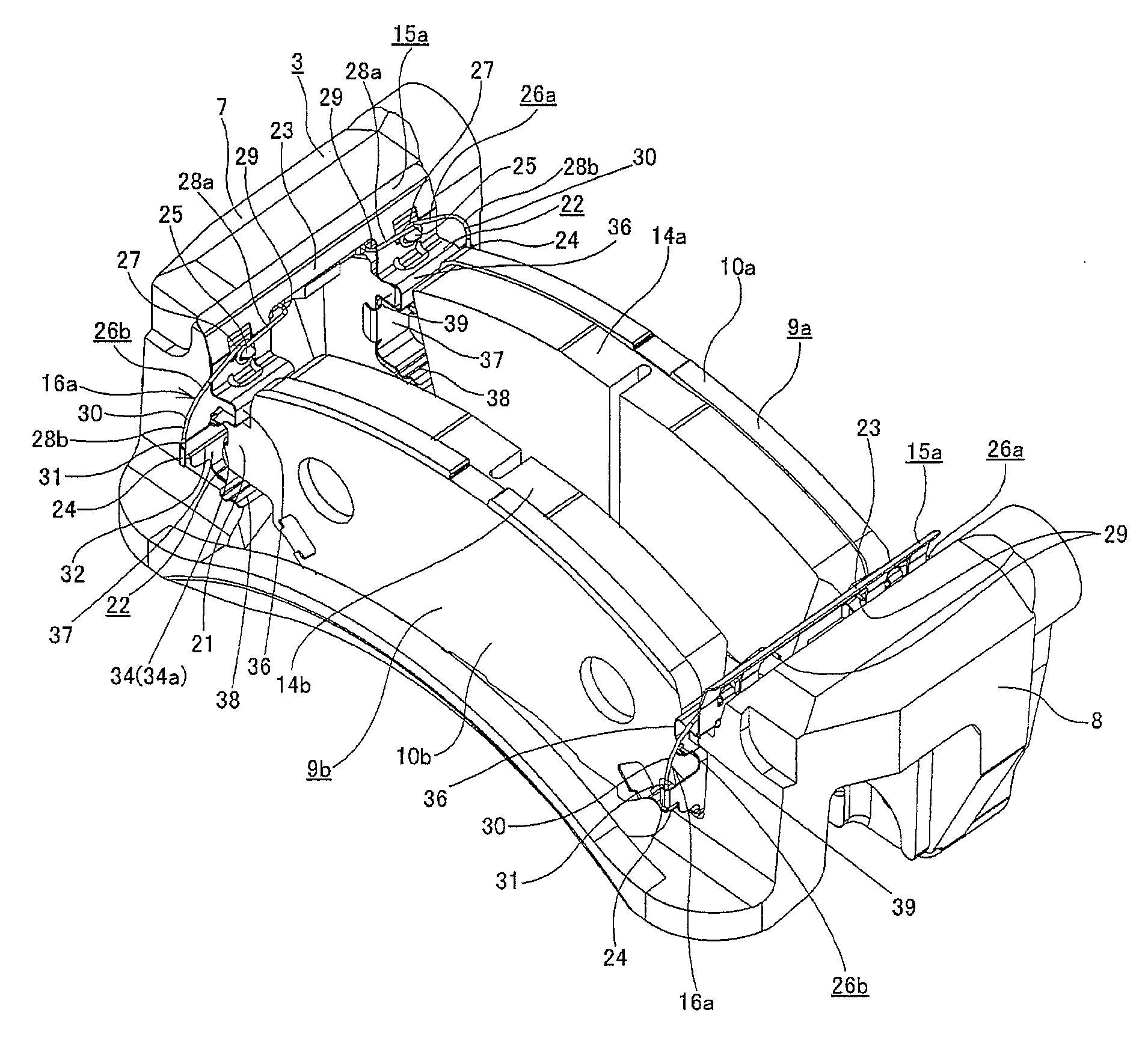
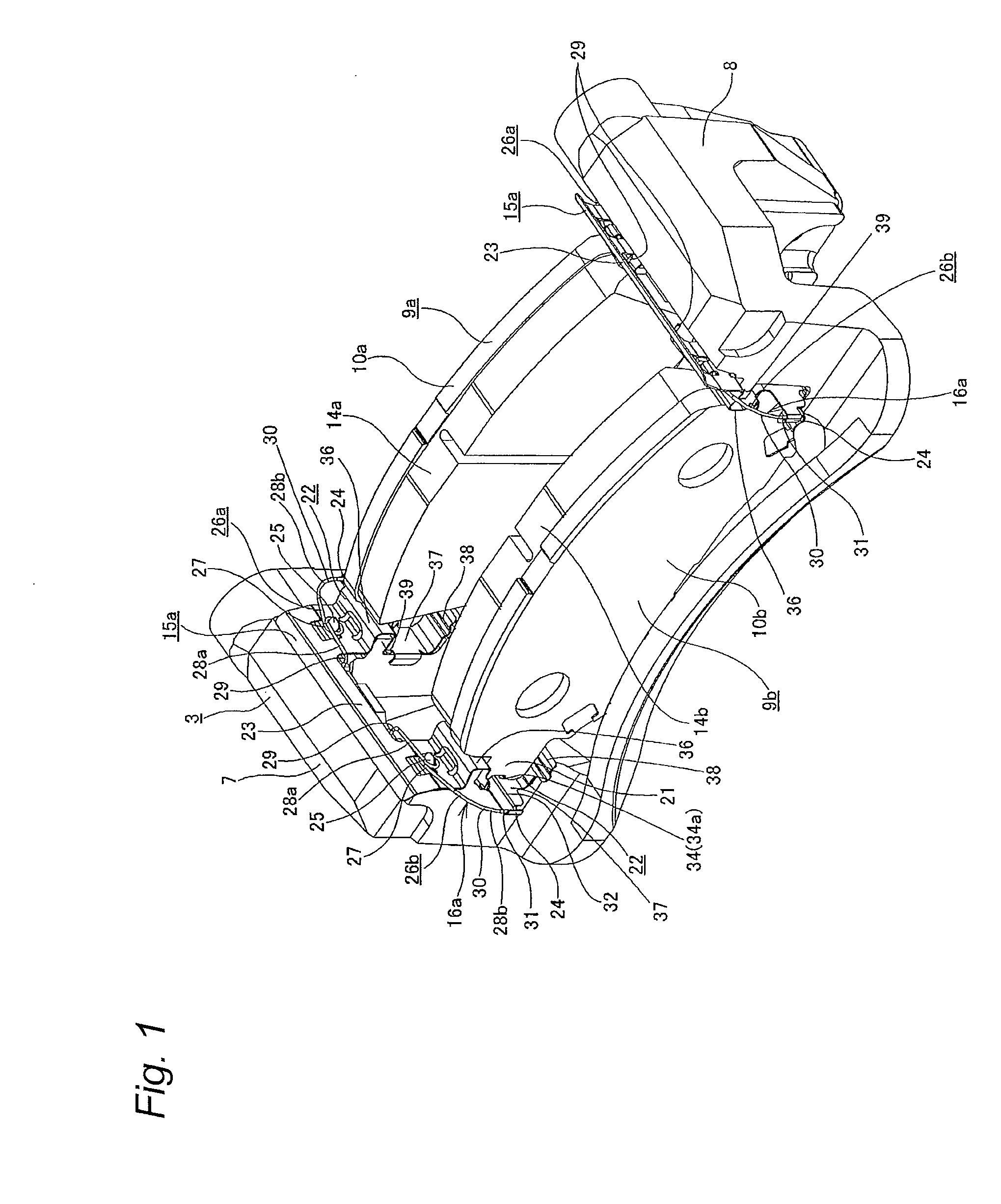
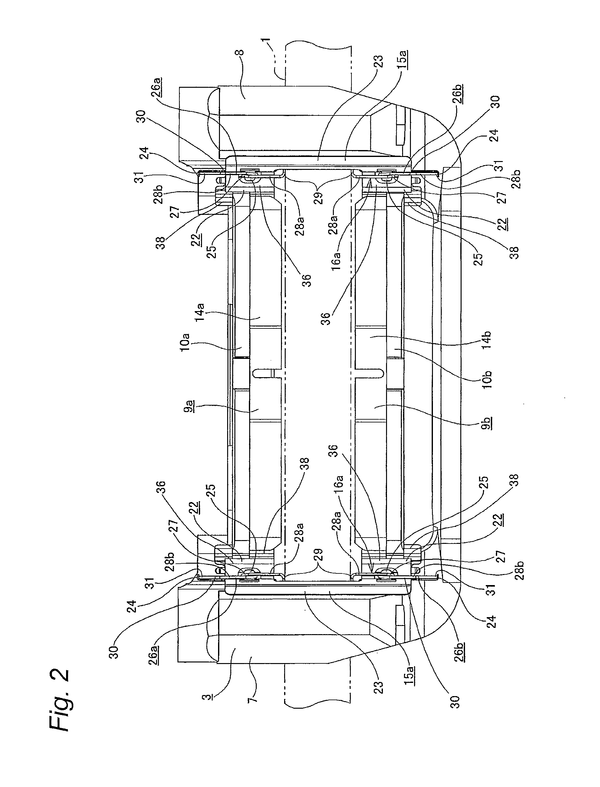
[0142]FIGS. 1 to 9 show a first embodiment of the invention. In the meantime, a feature of the invention relates to a structure of a pad clip 15a and a return spring 16a so as to easily perform a mounting operation of the pad clip 15a and the return spring 16a, including a structure of the first embodiment. The other structures and operational effects are the substantially same as those of the first example of the prior art. Thus, the illustration and description of the equivalent parts will be omitted or simplified. Hereinafter, features of the first embodiment of the invention will be described.

[0143]Also in the first embodiment, engaging protruding pieces 21, 21 that are provided at both circumferential end portions of pressure plates 10a, 10b configuring inner and outer pads 9a, 9b are engaged to engaging recesses 20, 20 that are formed at rotation input side and rotation output side engaging sections 7, 8, which are provided at both circumferential end portions of a support 3. ...

second embodiment

[0169]FIG. 9 shows a second embodiment of the invention. In the second embodiment, the return spring 16b is integrally formed by bending one wire rod, differently from the first embodiment. The return spring 16b has a shape connecting the leading end portion of the inner arm section 28a of inner spring element 26a and the leading end portion of the inner arm section 28a (for example, refer to FIG. 4) of the outer spring element 26b of the first embodiment. Specifically, the return spring 16b has a connection arm section 35 provided at an axially central portion with being put on the rotor 1 (refer to FIG. 2, for example), a pair of coil sections 27a, 27a continuing from both axial end portions of the connection arm section 35 and outer arm sections 28b, 28b having base portions continuing from the respective coil sections 27a, 27a. The configurations of the coil section 27a and the outer arm section 28b are the same as those of the first embodiment.

[0170]Also in the second embodimen...

third embodiment

[0173]FIGS. 10 to 18 show a third embodiment of the invention. The features of this embodiment are that the support structure of a return spring 16c to the pad clip 15b is different from the first embodiment. Since the basic structures of the pad clip 15b and the return spring 16c are the substantially same as those of the first embodiment, the description of the common parts are omitted or simplified. Hereinafter, the features of the third embodiment are described.

[0174]As shown in FIG. 16, also in the third embodiment, the pad clip 15b is configured by connecting diametrically outer end portions of a pair of axially spaced leg sections 22a, 22a by a connection section 23a. Particularly, in the third embodiment, the connection section 23a is formed with a pair of engaging notches 41, 41 for engaging parts (engaging sections 29a that will be described later) of the respective return springs 16c. The respective engaging notches 41, 41 are opened to a diametrically inner end edge of t...


PUM


Abstract

Disclosed is a structure such that when pad clips are to be mounted, it is possible to handle return springs and the pad clips as integral articles, thereby facilitating mounting work. Constraining sections are provided at both axial ends of each of the pad clips. Furthermore, the return springs are composed of inner spring elements and outer spring elements. These two types of spring elements are helical torsion springs provided with helical sections. Abutting sections are provided on the spring elements, respectively. The abutting sections are pressed against the inner surfaces of the constraining sections by elastic restoring forces. Moreover, the central axes of the coil sections are substantially oriented in the rotational direction of the rotor.

Description

TECHNICAL FIELD[0001]The invention relates to a floating disc brake, a method of assembling the same and an assembly of a pad clip and a return spring capable of smoothly returning a pad upon braking release to thus prevent friction between a lining of the pad and a side surface of a rotor upon non-braking, efficiently reducing a drag of the rotor upon non-braking and wear of the lining, improving assembling performance and reducing assembling cost.BACKGROUND ART[0002]Regarding a disc brake for braking a vehicle such as automobile, a floating disc brake has been widely known and has been actually used which supports a caliper so that it can displace in an axial direction (in the specification and the claims, an ‘axial direction’, a ‘diametrical direction’ and a ‘circumferential direction’ means an ‘axial direction’, a ‘diametrical direction’ and a ‘circumferential direction’ of a rotor, respectively) with respect to a support.[0003]FIG. 57 shows a floating disc brake, which is a fir...

Claims


Application Information

Patent Timeline
Patent Type & Authority Applications(United States)
IPC IPC(8): B60T1/06F16D65/092
CPCF16D55/227F16D65/0972F16D65/0975F16D2055/0008F16D65/0977F16D65/0978F16D65/0976F16D65/0043F16D2065/1396
Inventor MAEHARA, TOSHIFUMIKOBAYASHI, DAISUKE
Owner AKEBONO BRAKE IND CO LTD
Why Eureka
Try Eureka