
Chip package structure and method of manufacturing the same

a technology of chip package and chip package, which is applied in the direction of electrical equipment, semiconductor devices, semiconductor/solid-state device details, etc., can solve the problems of large degraded chip processing yield and ineffective full field image obtaining

Inactive Publication Date: 2013-01-31
SAMSUNG ELECTRONICS CO LTD
View PDF2 Cites 80 Cited by
  • Summary
  • Abstract
  • Description
  • Claims
  • Application Information

AI Technical Summary

Benefits of technology

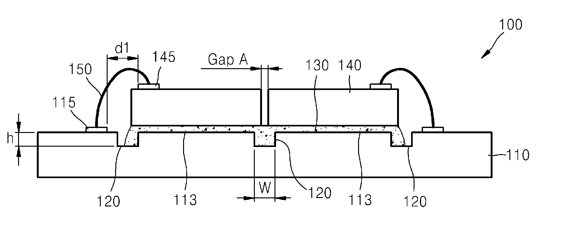
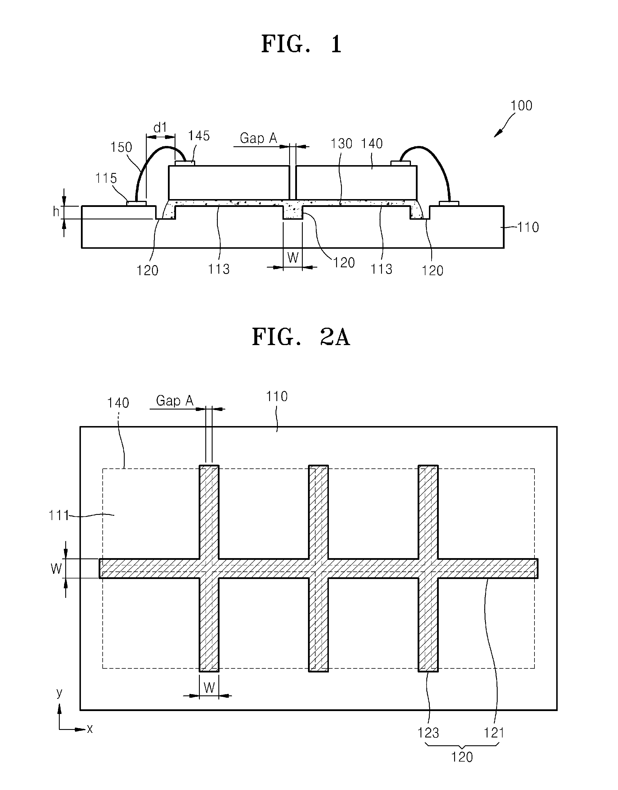
The patent describes a chip package structure and a method of fabricating it. The structure includes a substrate with grooves formed on it, and chips attached to the substrate using an adhesive layer. The grooves surround each chip and may cross each other. The width of each groove is equal to or greater than the gap between two adjacent chips. The adhesive layer may include a die attach material, such as epoxy or solder. The chips may be arranged in a 2D array or stacked on top of each other. The substrate may be made of organic, silicon, or ceramic. The method involves forming the grooves in the substrate and attaching the chips onto them, optionally using an underfill material between the substrate and the chips. The technical effects of this patent include improved cooling, reduced power consumption, and improved reliability of the chip package structure.

Problems solved by technology

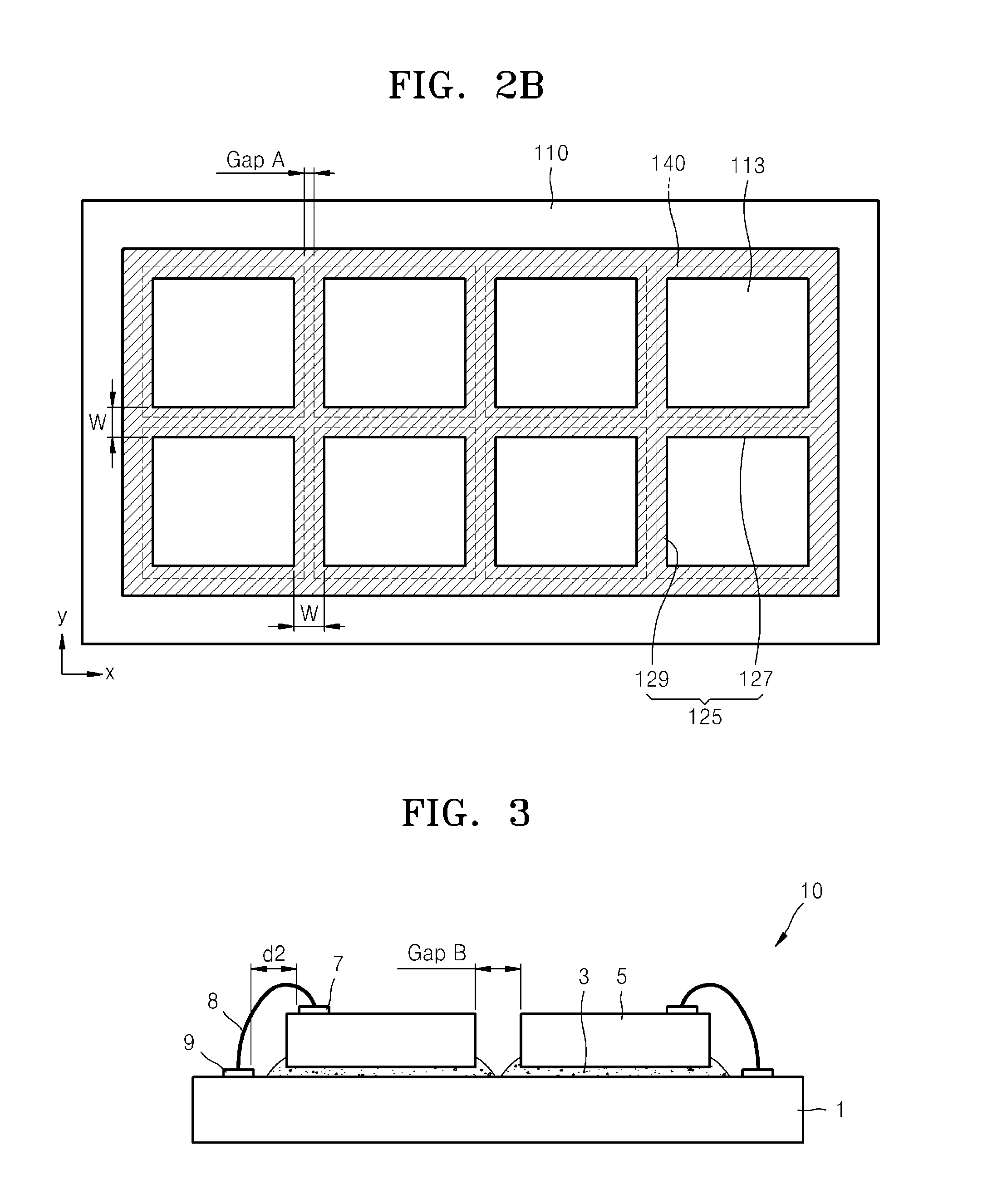
However, as the size of the chip increases, processing yield of the chip is greatly degraded.
Thus, it is not effective that the full field image is obtained by using one chip of a large size.

Method used


Image

  • Chip package structure and method of manufacturing the same
  • Chip package structure and method of manufacturing the same
  • Chip package structure and method of manufacturing the same

Examples


Embodiment Construction

[0039]Various example embodiments will now be described more fully with reference to the accompanying drawings in which some example embodiments are shown.

[0040]Detailed illustrative example embodiments are disclosed herein. However, specific structural and functional details disclosed herein are merely representative for purposes of describing example embodiments. This invention may, however, may be embodied in many alternate forms and should not be construed as limited to only the example embodiments set forth herein.

[0041]Accordingly, while example embodiments are capable of various modifications and alternative forms, embodiments thereof are shown by way of example in the drawings and will herein be described in detail. It should be understood, however, that there is no intent to limit example embodiments to the particular forms disclosed, but on the contrary, example embodiments are to cover all modifications, equivalents, and alternatives falling within the scope of the invent...


PUM


Abstract

A chip package structure includes a substrate in which a plurality of grooves are formed, an adhesive layer disposed on the substrate, and a plurality of chips attached to the adhesive layer. In addition, a method of fabricating the chip package structure includes forming a plurality of grooves in the substrate, dispensing a die attach material on a plurality of chip attaching regions between the plurality of grooves, and attaching a plurality of chips respectively on the plurality of chip attaching regions.

Description

CROSS-REFERENCE TO RELATED APPLICATION[0001]This application claims priority from Korean Patent Application No. 10-2011-0073772, filed on Jul. 25, 2011, in the Korean Intellectual Property Office, the disclosure of which is incorporated herein in its entirety by reference.BACKGROUND[0002]1. Field[0003]The present disclosure relates to chip package structures and methods of manufacturing chip package structures, and more particularly, to chip package structures in which a groove is formed in a substrate in order to reduce a gap between chips, and methods of manufacturing the chip package structures.[0004]2. Description of the Related Art[0005]An image sensor chip is a chip capable of converting an input optical image into an electric signal, and an ultrasonic transducer chip is a chip capable of converting an ultrasonic signal into an electric signal. Recently, research into obtaining a full field image of a large size by using the above chips has been conducted. In order to obtain a...

Claims


Application Information

Patent Timeline
IPC IPC(8): H01L23/52H01L21/50
CPCH01L23/13H01L21/563H01L24/32H01L2224/32225H01L2224/48227H01L2224/73204H01L2924/0132H01L2224/45139H01L24/83H01L24/16H01L24/29H01L24/45H01L24/48H01L24/92H01L25/0655H01L25/0657H01L2224/0401H01L2224/04042H01L2224/2919H01L2224/45124H01L2224/45144H01L2224/45147H01L2224/48091H01L2224/73265H01L2224/83192H01L2224/92125H01L2924/10253H01L2924/1461H01L2924/15159H01L2924/157H01L2924/15787H01L2924/01013H01L2924/01014H01L2924/01029H01L2224/27013H01L2224/26175H01L2224/97H01L24/97H01L2224/13111H01L2224/13113H01L2224/13116H01L2224/1312H01L2224/13139H01L2224/13147H01L2224/16238H01L2924/01047H01L2924/01079H01L2924/00014H01L2924/00012H01L2224/16225H01L2924/00H01L2924/0665H01L2224/81H01L2224/83H01L2924/15747H01L2924/12042H01L24/73H01L2224/83385H01L2224/92247H01L25/16H01L23/12
Inventor LEE, BAIK-WOOSHIN, HYUNG-JAE
Owner SAMSUNG ELECTRONICS CO LTD
Learn More