Method for the surface treatment of large parts, gripper of parts suitable for implementing such a method, use of said gripper and treatment cubicle

a technology for large parts and grippers, applied in the direction of large fixed members, baking, food shaping, etc., can solve the problem of small imperfections and achieve the effect of improving the surface treatment

Inactive Publication Date: 2013-01-31
CO PLASTIC OMNIUM
View PDF4 Cites 15 Cited by
  • Summary
  • Abstract
  • Description
  • Claims
  • Application Information

AI Technical Summary

Benefits of technology

[0011]The present invention provides a method of performing surface treatment on parts of large dimensions that present a certain amount of flexibility that makes them geometrically unstable in shape in the event of being moved, the treatment being performed with the help of at least one local treatment device, and in which method a part having a surface for treatment is moved past the local treatment device with its surface for treatment facing towards the local treatment device, wherein the part is gripped at the end of a robot arm, the local treatment device is kept stationary relative to the robot, the part is deformed by imparting a deformed configuration thereto in which its deformable portions impose a stable geometrical shape on the part as a whole, and the part is moved by the robot arm relative to local treatment device in such a manner as to cause all of its surface for treatment to move past the local treatment device while the part is being held in its deformed configuration.
[0016]The result obtained by the invention, when the local treatment consists in spraying droplets or solid particles, is better uniformity in the shapes, positions, and densities of the droplets or solid particles at the moment they impact against the surface for treatment, thereby providing a layer of constant thickness with maximum smoothness and brightness.
[0018]In addition, since the conditions under which paint is applied are improved, the paint transfer coefficient is also improved, thereby leading to a smaller quantity of paint being lost, i.e. to a saving of material.
[0020]A first advantage of this implementation is that the droplets or solid particles conserve their density, their shapes, and their dimensions that are optimized for obtaining good quality paint.
[0021]A second advantage is that keeping the paint spray nozzle stationary makes it possible to use a device that need not necessarily be light in weight, or flexible, or compact, thereby widening the range of devices that can be used for this purpose and consequently making it possible to use equipment that is selected solely on the criteria of the quality with which it applies paint. Similarly, there is no longer any need for the paint feed network to be capable of following the movements of the spray device, since the device is stationary.
[0029]in a second position, holding the part in a deformed configuration in which its deformable portions cause the part as a whole to take up a shape that is stable.

Problems solved by technology

Nevertheless, although it provides high-quality results, it gives rise to small imperfections.

Method used


Image

  • Method for the surface treatment of large parts, gripper of parts suitable for implementing such a method, use of said gripper and treatment cubicle
  • Method for the surface treatment of large parts, gripper of parts suitable for implementing such a method, use of said gripper and treatment cubicle
  • Method for the surface treatment of large parts, gripper of parts suitable for implementing such a method, use of said gripper and treatment cubicle

Examples


Embodiment Construction

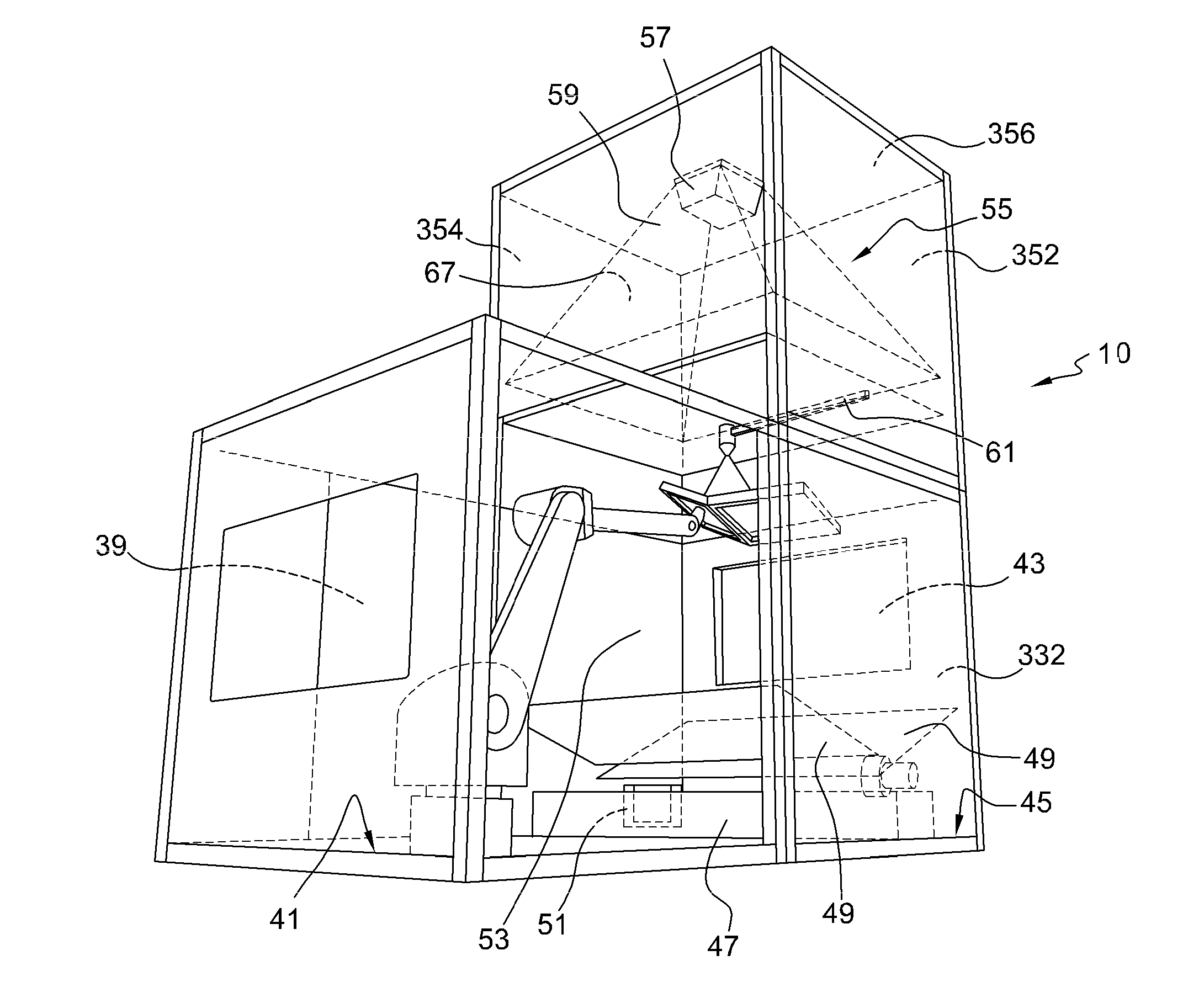
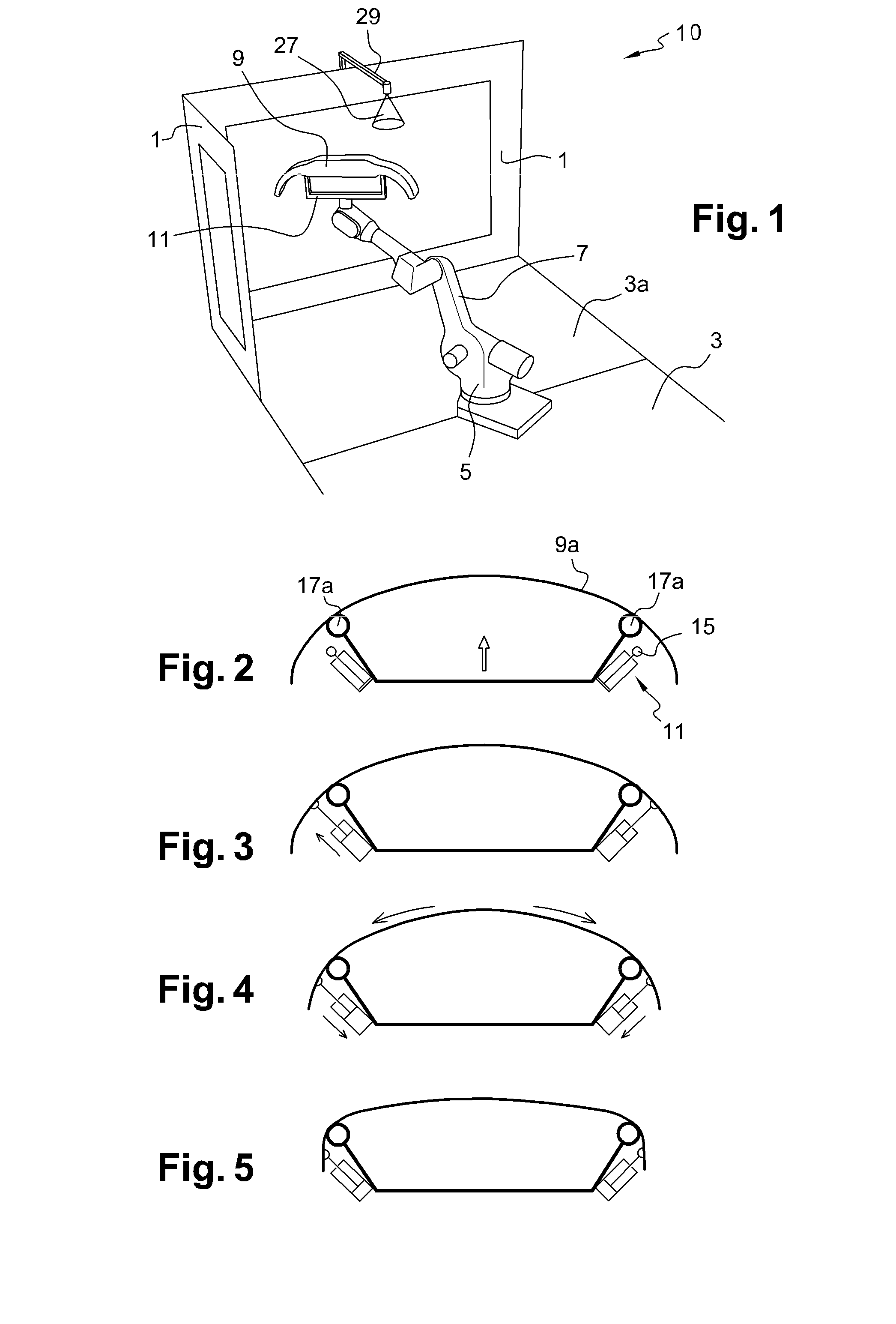
[0059]In FIG. 1, there can be seen a painting booth or installation 10 comprising vertical partitions 1, a ceiling (not shown), and a floor 3, including a gridded portion 3a connected to air suction. A more complete booth 10, made up of three portions, is described with reference to FIGS. 8 and 9. The booth 10 comprises an enclosure containing a painting installation 10.

[0060]The floor 3 carries a manipulator robot 5 having a movable arm 7 with six degrees of freedom. Such a robot 5 is in widespread use in the automobile industry and is not described herein. By way of example, the P250 model from the supplier FANUC Robotics America, Inc. of Rochester Hills, Mich., USA, is suitable for implementing the invention. The robot 5 carries a part of large dimensions, and in this example the part is a bumper skin 9.

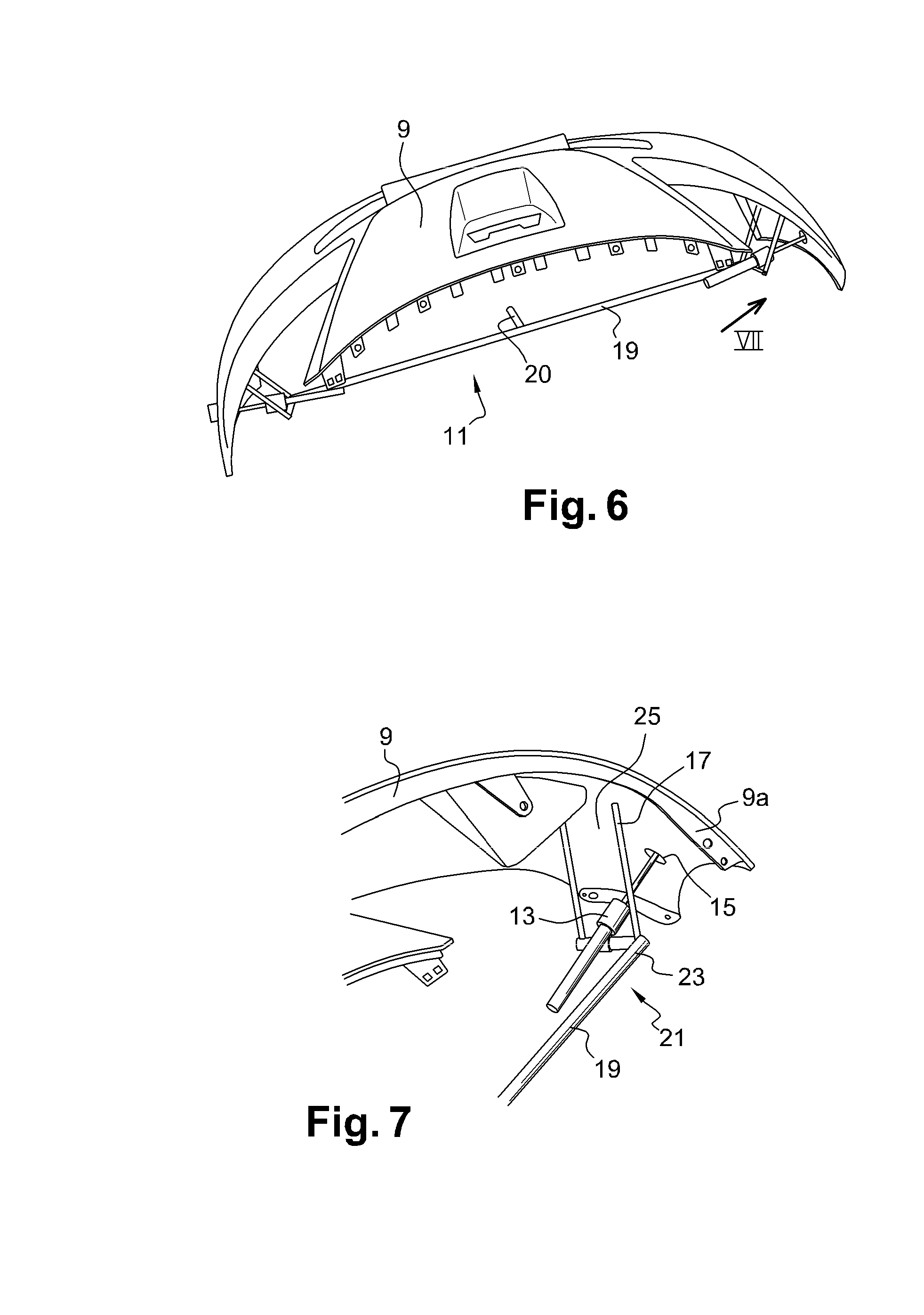
[0061]The end of the arm 7 carries a “universal” gripper, made up of a structure 11, two pneumatic actuators 13, two suction cups 15 constituting holder means, and four abutments ...


PUM

PropertyMeasurementUnit
lengthaaaaaaaaaa
heightaaaaaaaaaa
heightaaaaaaaaaa

Abstract

A system and method of painting parts of large dimensions that present a certain amount of flexibility that makes their shape geometrically unstable in the event of being moved. The surface of a part is moved in front of a paint spray device by an arm of a robot, while the spray device remains stationary relative to the robot and while the part is being deformed. Other elements include a gripper for gripping parts of large dimensions, the gripper being adapted to implement the method; an installation; and a booth for performing surface treatment of parts.

Description

CROSS-REFERENCE TO RELATED APPLICATIONS[0001]This application is the U.S. National Phase application of PCT / FR2010 / 052927 filed Dec. 28, 2010, which claims priority to French Application No. 0959647 filed Dec. 29, 2009, which applications are incorporated herein by reference and made a part hereof.BACKGROUND OF THE INVENTION[0002]1. Field of the Invention[0003]The present invention relates to a method of performing surface treatment on parts of large dimensions, in particular motor vehicle bodywork parts, and to a parts gripper that is adapted to implement such a method.[0004]2. Description of the Related Art[0005]Bodywork parts are usually painted by locally spraying paint in the form of droplets or solid particles onto the parts for painting, which parts are carried by moving supports that travel past paint spray stations while presenting the parts in a constant orientation that is appropriate for their treatment. In other words, the parts are moved in translation during painting ...

Claims


Application Information

Patent Timeline
Patent Type & Authority Applications(United States)
IPC IPC(8): B05C13/00B05D1/02B05C9/10B05D3/12B05B14/462B05B16/00B05B16/40B05B16/60
CPCB05B15/1207B05B15/1214B05B15/1222B05B13/0221B05B15/1266B05B15/1288B05B15/1229B05B16/20B05B16/60B05B14/48B05B14/462B05B16/90B05B16/40Y02P70/10
Inventor TRESSE, DAVID
Owner CO PLASTIC OMNIUM
Why Eureka
Try Eureka