Light emitting device

Inactive Publication Date: 2013-01-31
PHOENIX ELECTRIC CO
View PDF2 Cites 2 Cited by
  • Summary
  • Abstract
  • Description
  • Claims
  • Application Information

AI Technical Summary

Benefits of technology

The present invention is a light emitting device that protects the power circuit from the heat of LEDs. It has a flexible shape and can avoid corrosion and electrical leakage even in outdoor use. The heat conduction is prevented, resulting in a low temperature for the power circuit. The device is designed to prevent accumulation of rain water and can be easily installed. Its technical effects are improved durability, flexibility, and safety.

Problems solved by technology

But the light emitting devices described in the Patent Document 1 and 2 as referred to above still have other issues.
Consequently, to design the shape of the glove becomes too difficult and complicated.
The accumulated rain water or the like causes corrosion and electrical leakage.

Method used


Image

  • Light emitting device
  • Light emitting device
  • Light emitting device

Examples


Embodiment Construction

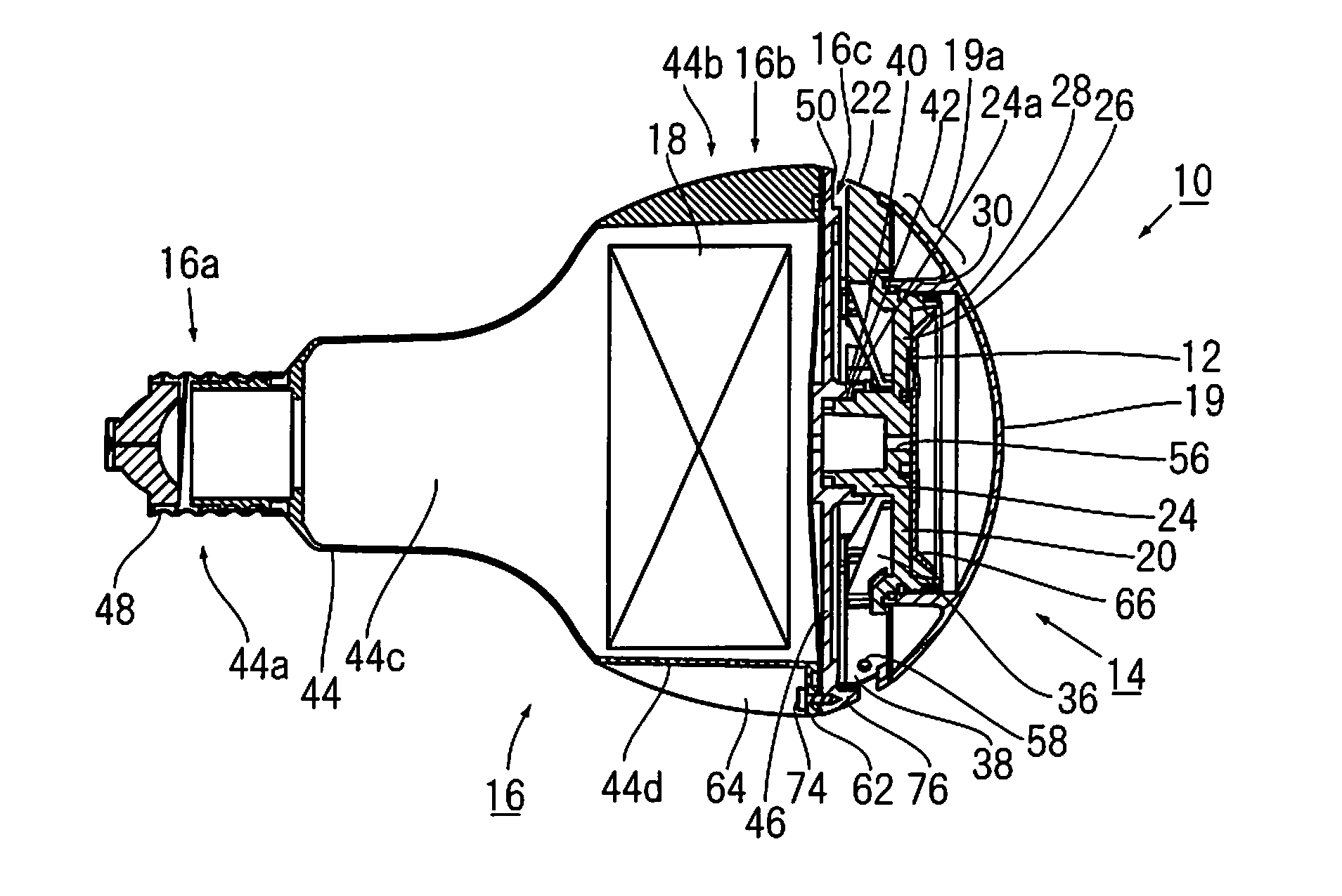
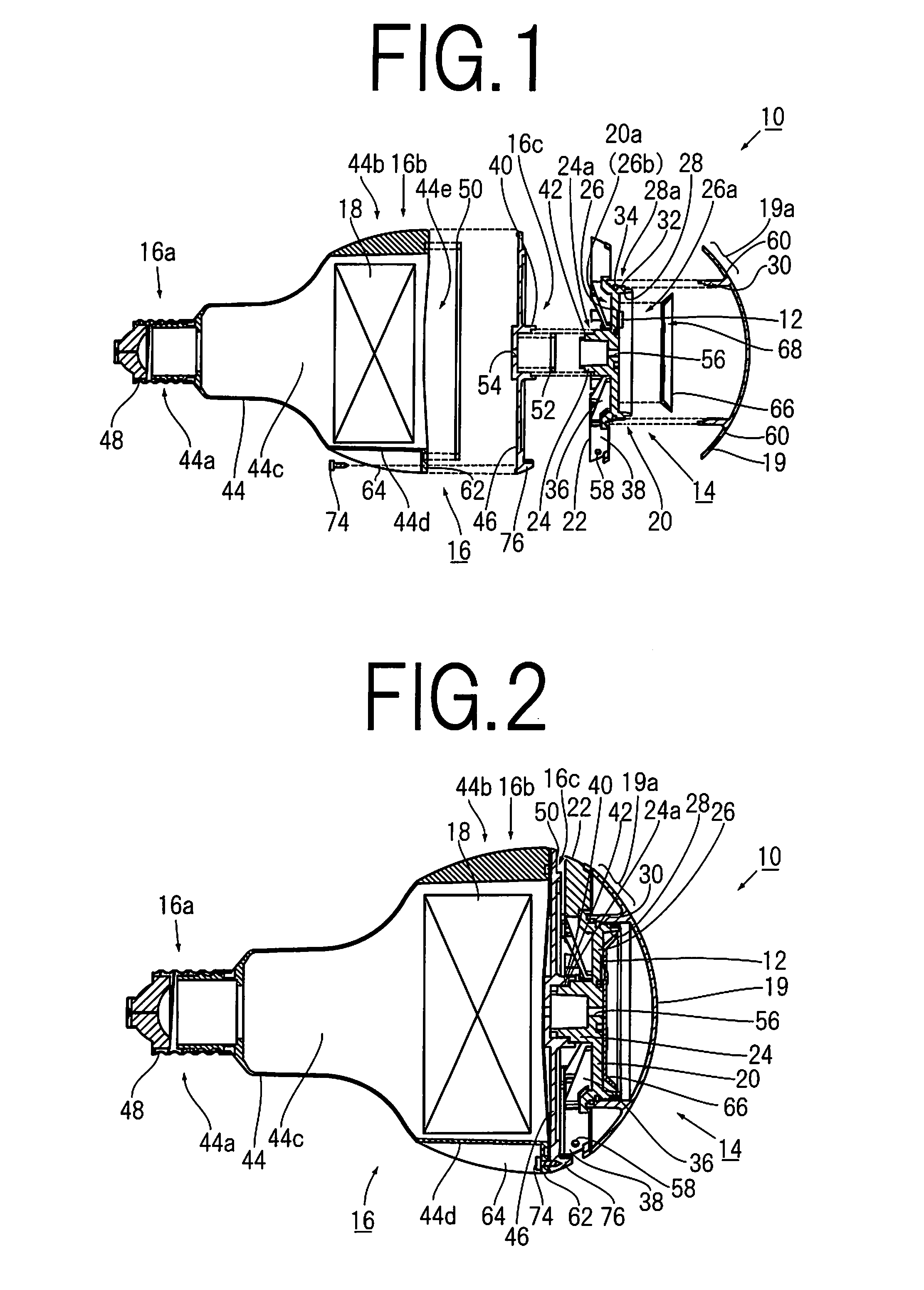
[0032]Hereinafter, a light emitting device of the present invention will be described based on a embodiment illustrated in drawings.

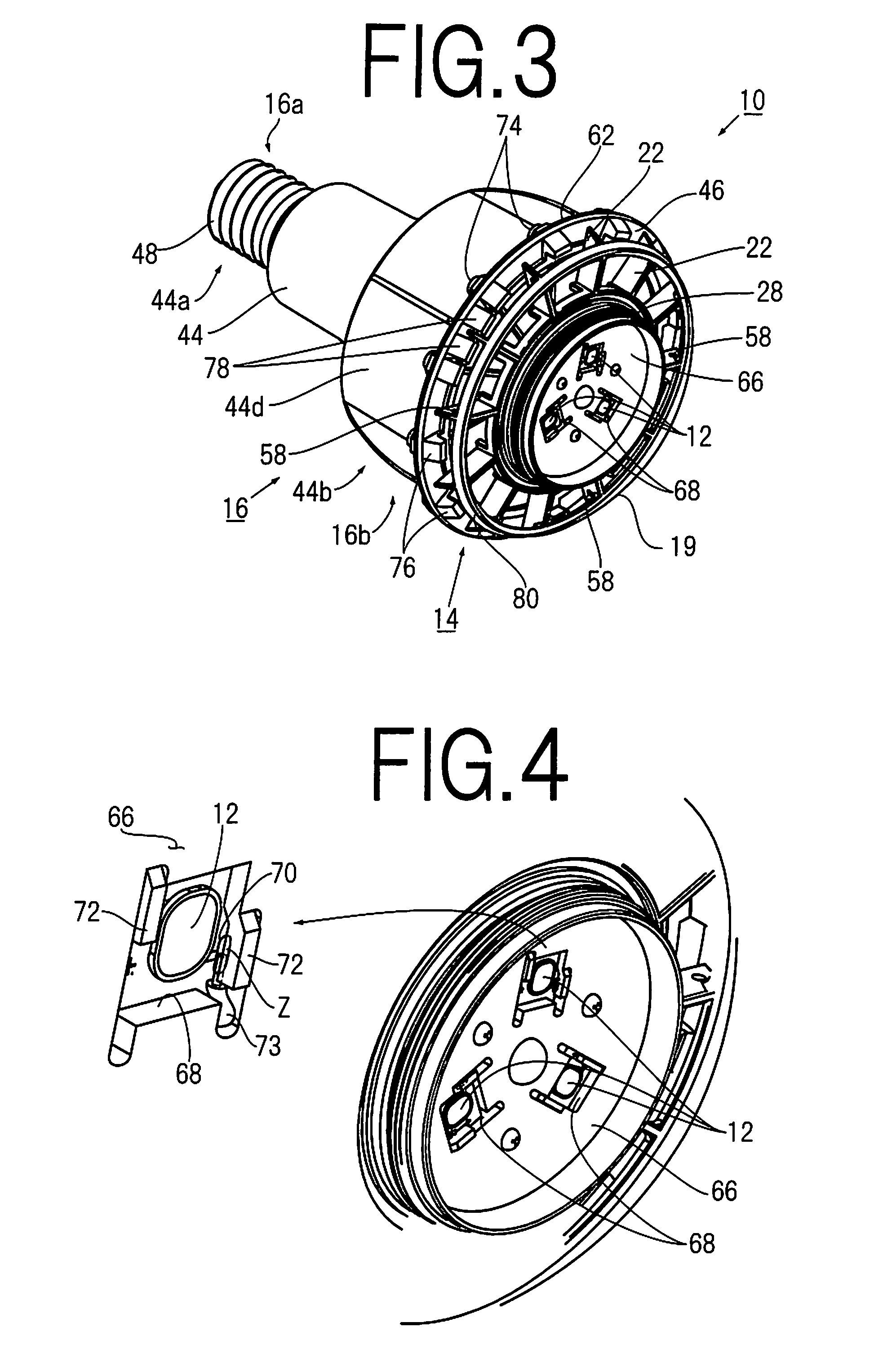
[0033]The light emitting device 10, as shown in FIG. 1 to FIG. 3, comprises: LEDs 12; an LED holder 14; a body 16; a power circuit 18; and a front cover 19 (as necessary).

[0034]The LEDs 12 are semiconductor devices which emit light by applying predetermined voltage, and the LEDs 12 are mounted on an upper surface of an LED mount 20 of the LED holder 14.

[0035]Each light emitting surface of the LEDs 14 in this embodiment is of almost a shape of an ellipse. There is no limitation on the shape. A shape of rectangle or circularity may be accepted.

[0036]Furthermore, the number of the LEDs 12 is not limited. Three LEDs 12, as shown in FIG. 3, one LED 12, two LEDs 12, or four or more LEDs 12 can be mounted on the LED holder 14.

[0037]A light distribution pattern of the LED 12 is Lambertian type. In the light distribution pattern of the Lambertian type, almost of...


PUM


Abstract

A light emitting device comprises: an LED; a LED holder having a LED mount, a radiation fin provided on a back side or a periphery of the LED mount, and an engaging part projecting from a center of the back side of the LED mount; a power circuit supplying drive power to the LED; and a body having an inner space for accommodating the power circuit, one end, and the other end where the LED holder is fixed, wherein the other end of the body has an engaged part engaged to the engaging part of the LED holder, and holding the LED mount and the radiation fin in a state of separation from the body; heat conductivity of the LED mount and the radiation fin is higher than that of the engaged part of the body.

Description

BACKGROUND OF THE INVENTION[0001]1. Field of the Invention[0002]The present invention relates to a light emitting device with an LED designed for mainly outdoor use and used as substitute for an incandescent lamp, e.g. a mercury lamp, a halogen lamp or the like.[0003]2. Description of Related Art[0004]A light-emitting diode “LED”, which has advantages such as low power consumption and long life as against a conventional incandescent lamp (for example, a mercury lamp or a halogen lamp), is widely used, because people become more ecology conscious. And people consider that using the LED is one policy for the energy-saving strategies. Particularly, it is highly required to use the LED as an alternate item of the incandescent lamp.[0005]Such a request is not only for an indoor type light emitting device but for a light emitting device for outdoor use, e.g. for lighting a sign board.[0006]A general LED emits light by several volts of DC voltage. Consequently, when a light emitting device...

Claims


Application Information

Patent Timeline
IPC IPC(8): H01J7/24H01J7/44
CPCF21Y2101/02F21K9/135F21V29/773F21V29/74F21K9/90F21K9/232F21Y2115/10F21V29/00F21V17/10
Inventor MATSUMOTO, RYUTAKOKADO, HARUO
Owner PHOENIX ELECTRIC CO
Why Eureka
Try Eureka