
LED driving circuit package

a technology of led driving circuit and led light, which is applied in the direction of gas-filled discharge tubes, electric discharge lamps, solid cathodes, etc., can solve the problems of not meeting the requirements of led lighting, not meeting the power factor and thd, and commercial ac power may not provide ideal sinusoidal wave form of ac voltag

Active Publication Date: 2013-01-31
SEOUL SEMICONDUCTOR
View PDF14 Cites 39 Cited by
  • Summary
  • Abstract
  • Description
  • Claims
  • Application Information

AI Technical Summary

Benefits of technology

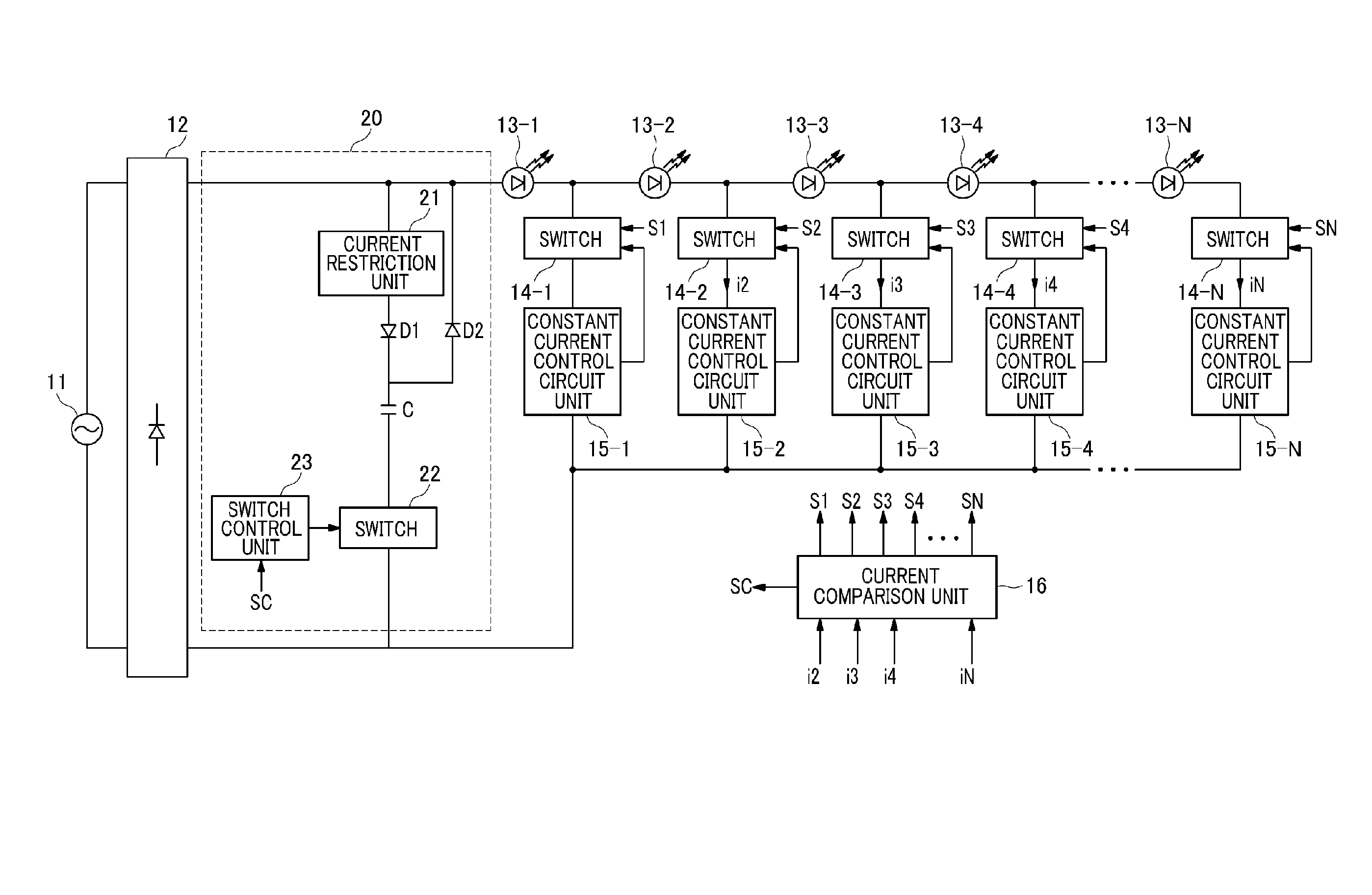
The present invention provides an LED driving circuit package that includes a rectification unit to receive an AC power voltage and rectify it to generate a ripple voltage, an LED driving switching unit including a plurality of switch units and a plurality of current control units, a low voltage control unit including a circuit power supply unit to generate low voltage power, a voltage detection unit to detect the magnitude of the ripple voltage, a reference frequency generation unit to operate using low voltage power to generate a reference frequency, and a reference pulse generation unit to operate using low voltage power to generate a reference pulse for controlling the operation of the LED driving switch unit according to the reference frequency and the magnitude of the voltage detected by the voltage detection unit. The LED driving circuit package provides an efficient and effective solution for driving LED devices.

Problems solved by technology

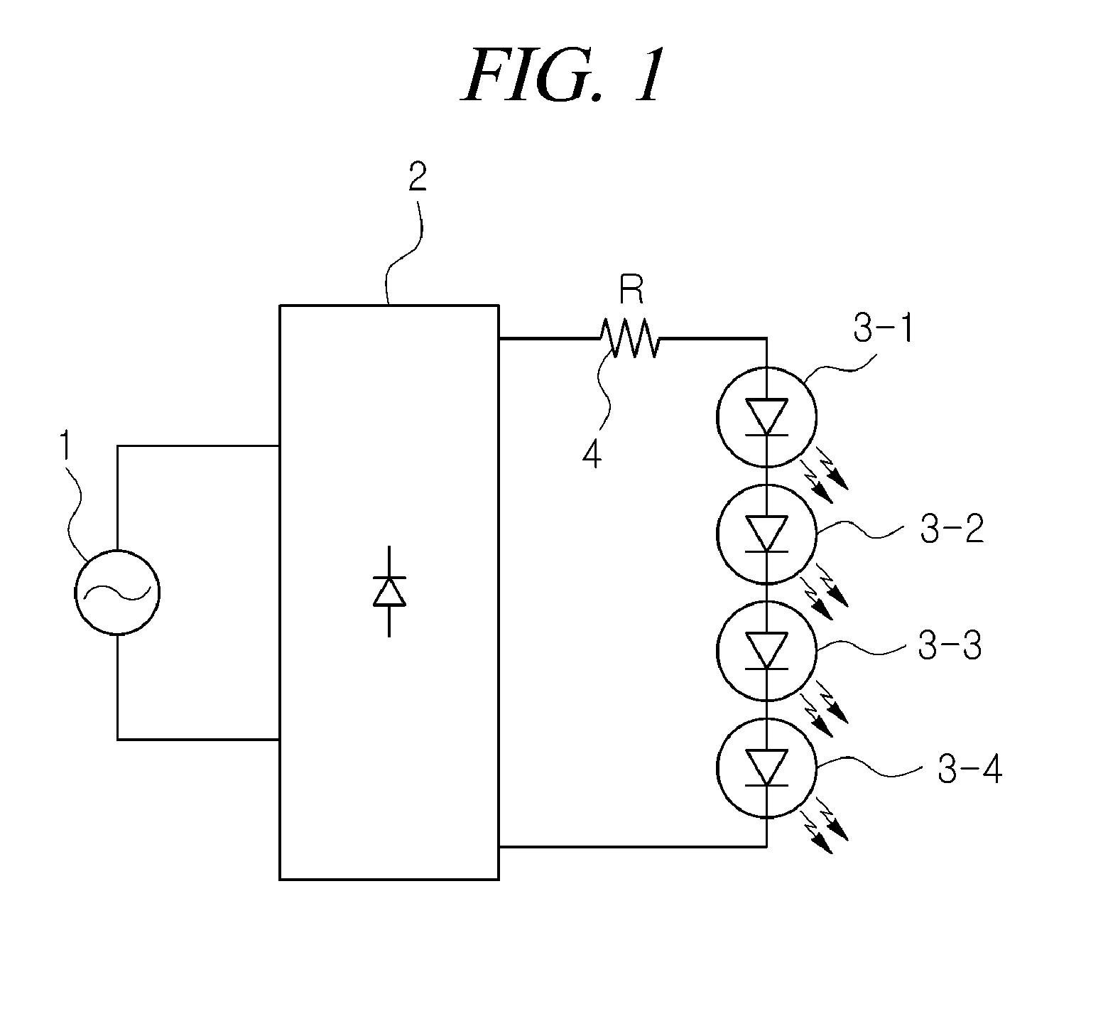
In such a conventional LED luminescence apparatus using AC power, LED driving current provided to the LEDs may not have a complete sinusoidal wave form and there may be a phase difference between the LED driving current and AC voltage, and therefore a problem may arise in that electrical characteristics, including power factor and THD, do not fulfill requirements for LED lighting.
However, since the driving efficiency and light output characteristics of high-voltage driven LEDs may be determined depending on the driving voltage Vf of the LEDs, the simple reduction in the driving voltage Vf of the LEDs may cause the problem of not fulfilling the power factor and the THD that are presented in the LED lighting standard.
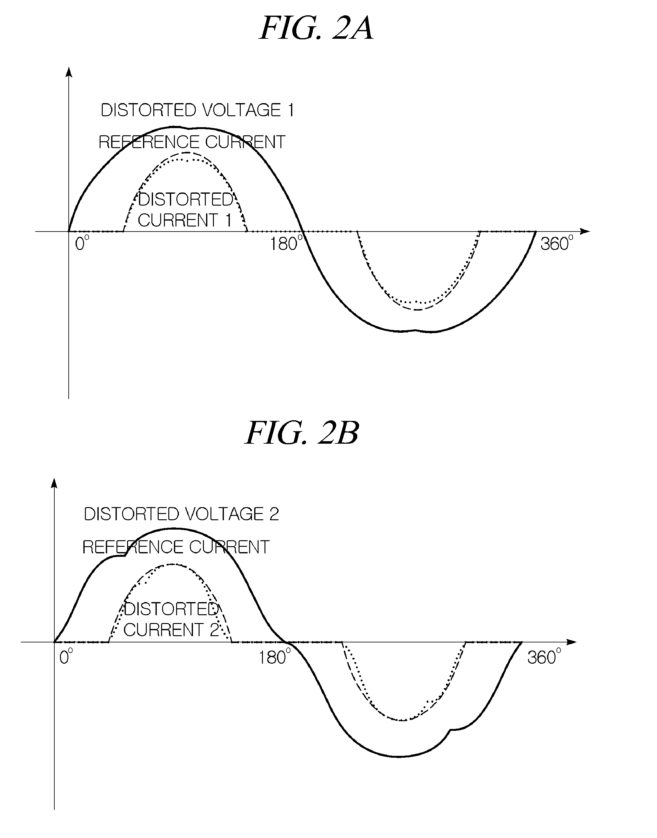
Furthermore, commercial AC power may not provide AC voltage in ideal sinusoidal wave form.
That is, the problem of the magnitude of commercial AC voltage being higher or lower than that of a reference voltage in ideal sinusoidal wave form arises, and the waveform thereof may be distorted by harmonics.

Method used


Image

  • LED driving circuit package
  • LED driving circuit package
  • LED driving circuit package

Examples


Embodiment Construction

[0061]The invention is described more fully hereinafter with reference to the accompanying drawings, in which exemplary embodiments of the invention are shown. This invention may, however, be embodied in many different forms and should not be construed as limited to the exemplary embodiments set forth herein. Rather, these exemplary embodiments are provided so that this disclosure is thorough, and will fully convey the scope of the invention to those skilled in the art. In the drawings, the size and relative sizes of layers and regions may be exaggerated for clarity. Like reference numerals in the drawings denote like elements.

[0062]It will be understood that when an element or layer is referred to as being “on” or “connected to” another element or layer, it can be directly on or directly connected to the other element or layer, or intervening elements or layers may be present. In contrast, when an element is referred to as being “directly on” or “directly connected to” another elem...


PUM


Abstract

An LED driving circuit package includes a rectification unit to receive an AC power voltage and rectify the AC power voltage to generate a ripple voltage, an LED driving switching unit including a plurality of switch units and a plurality of current control units. The LED driving circuit package further includes a low voltage control unit including a circuit power supply unit to generate low voltage power, a voltage detection unit to detect a magnitude of the ripple voltage, a reference frequency generation unit to generate a reference frequency, and a reference pulse generation unit to generate a reference pulse for controlling the operation of the LED driving switch unit according to the reference frequency and a magnitude of the voltage detected by the voltage detection unit.

Description

CROSS REFERENCE TO RELATED APPLICATIONS[0001]This application claims the benefit of U.S. Provisional Patent Application Nos.: 61 / 437,288, filed on Jan. 28, 2011; 61 / 437,296, filed on Jan. 28, 2011; 61 / 437,932, filed on Jan. 31, 2011; 61 / 438,304, filed on Feb. 1, 2011; 61 / 438,308, filed on Feb. 1, 2011; 61 / 442,732, filed on Feb. 14, 2011; 61 / 467,782, filed on Mar. 25, 2011; and 61 / 565,574, filed on Dec. 1, 2011, which are all hereby incorporated by reference for all purposes as if fully set forth herein.BACKGROUND OF THE INVENTION[0002]1. Field of the Invention[0003]Exemplary embodiments of the present invention relate to a Light-Emitting Diode (LED) luminescence apparatus using Alternating Current (AC) power and, more particularly, to an LED luminescence apparatus that is capable of improving power factor and Total Harmonics Distortion (THD) and effectively dealing with the distortion and commercial AC voltage and variation in the magnitude thereof. Exemplary embodiments of the pres...

Claims


Application Information

Patent Timeline
IPC IPC(8): H05B37/02H01L33/62H01J7/24H05B44/00
CPCH05B33/0818H05B33/083Y02B20/347H01L2224/05554H01L2224/32225H01L2224/48091H01L2224/48137H01L2224/48227H01L2224/45139H01L2924/181H01L2224/4813H01L2224/49113H05B45/44Y02B20/30H05B45/395H05B47/10H05B45/14H01L2924/00011H01L2924/00014H01L2924/00012H01L2924/01049H05B45/48H01L2924/00
Inventor JONG, YOUNG DOKANG, HYUN GUJUNG, HYE MANLEE, KANG NYUNG
Owner SEOUL SEMICONDUCTOR
Learn More