
Current sensor

a current sensor and sensor technology, applied in the field of sensors, can solve the problems of reducing the overall accuracy of the measurement of isub>dc/sub>, reducing the size of the air gap b>14, and generating core losses and heat in the cor

Inactive Publication Date: 2013-01-31
ABB INC
View PDF5 Cites 7 Cited by
  • Summary
  • Abstract
  • Description
  • Claims
  • Application Information

AI Technical Summary

Benefits of technology

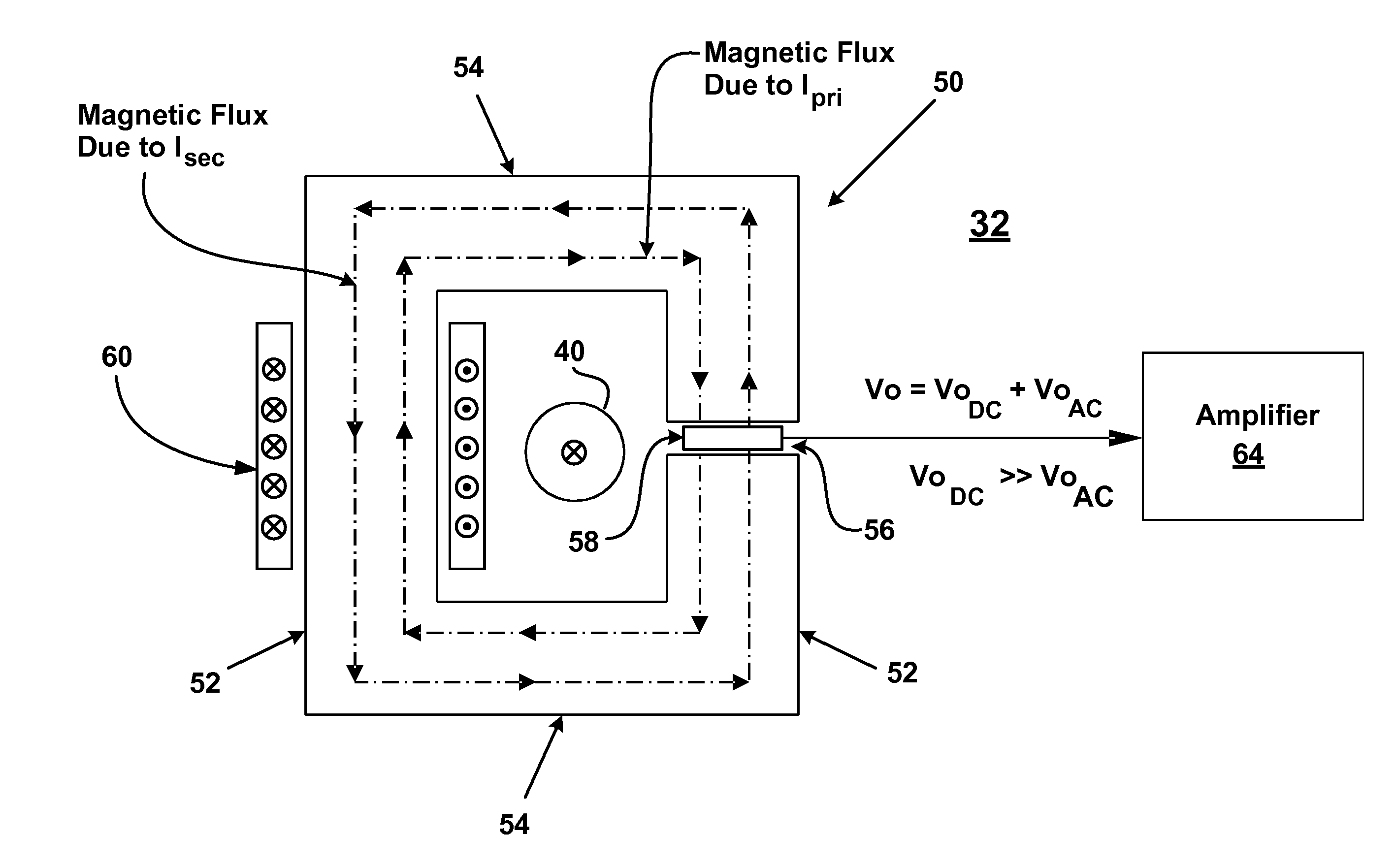
The present invention provides a current sensor for measuring DC current in a primary conductor that also carries AC current. The sensor has a ferromagnetic core with an air gap containing a magnetic flux sensor. A secondary winding is connected to the core with a negligible impedance at frequencies of the AC current. The air gap has a narrow width to minimize interference with the magnetic flux sensor. The invention also includes an inverter system for connecting primary conductors to a utility network with current sensors for monitoring the current. These sensors have the described construction to ensure accurate and reliable measurement of the DC current.

Problems solved by technology

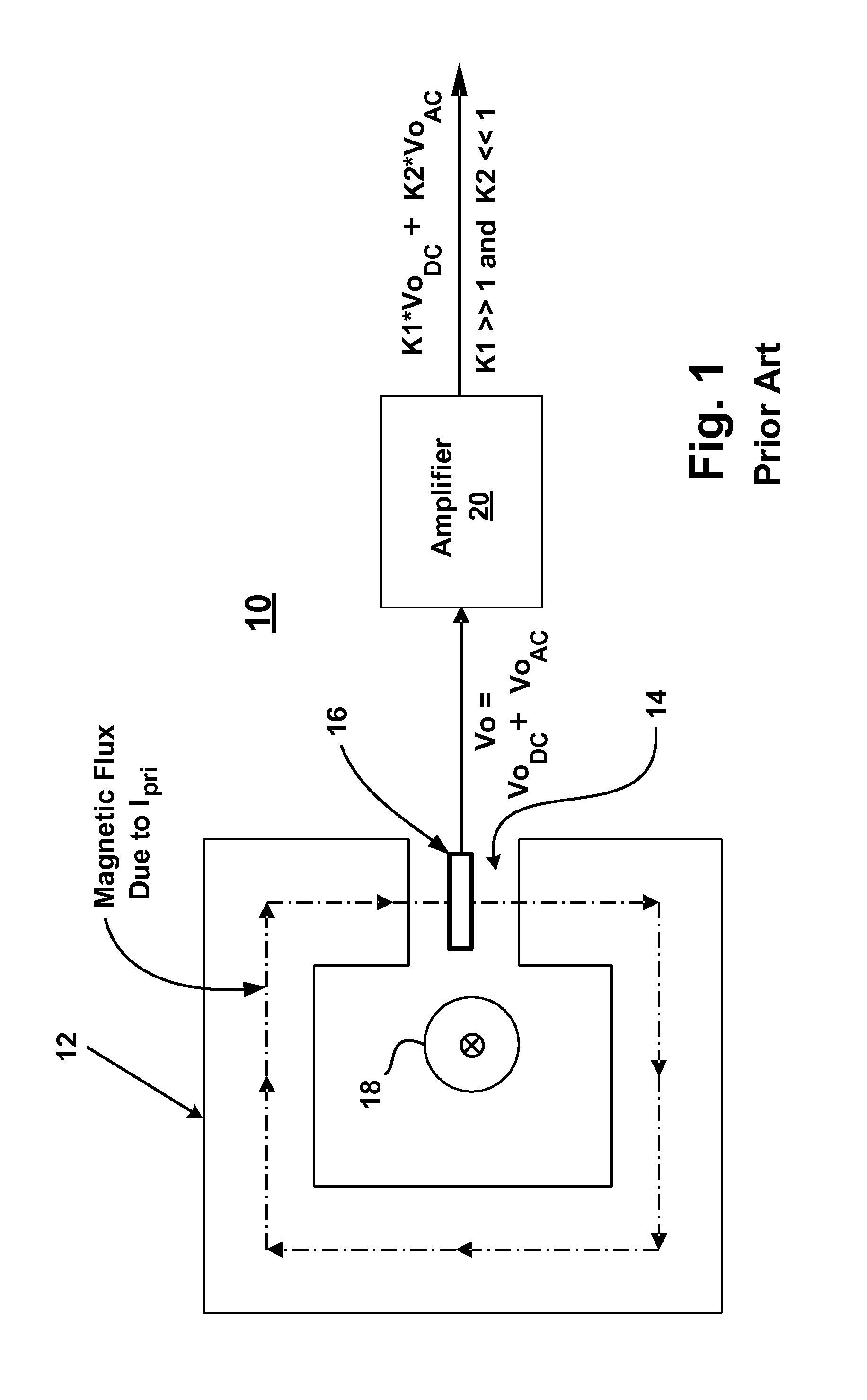
The foregoing system has a number of disadvantages when the AC current is significantly greater than the DC current in the primary conductor 18.
One disadvantage is the size of the air gap 14.
Another disadvantage is the large amount of AC component of flux passing through the core 12, which produces core losses and heat in the core 12.
Still another disadvantage is that the amplifier 20 used to extract and amplify the small signal Vodc, also amplifies error components (e.g. offset voltage) of the Hall element 16, thereby reducing the overall accuracy of the measurement of Idc.

Method used


Image

  • Current sensor
  • Current sensor
  • Current sensor

Examples


Embodiment Construction

[0018]It should be noted that in the detailed description that follows, identical components have the same reference numerals, regardless of whether they are shown in different embodiments of the present invention. It should also be noted that in order to clearly and concisely disclose the present invention, the drawings may not necessarily be to scale and certain features of the invention may be shown in somewhat schematic form.

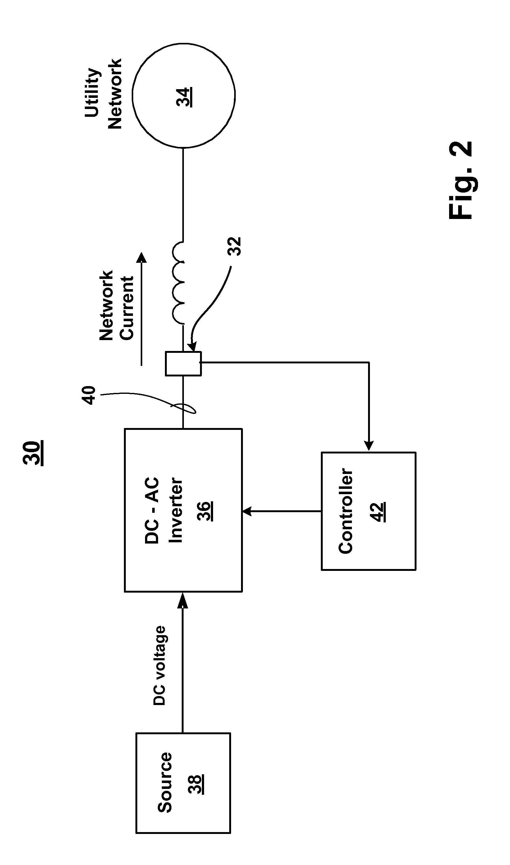
[0019]Referring now to FIG. 2, there is shown a utility interactive inverter system 30 that utilizes one or more current sensors 32 embodied in accordance with the present invention. The inverter system 30 has particular utility for tying renewable energy sources, like wind turbines, fuel cells, and photovoltaic solar cells, to an AC utility network 34. The inverter system 30 comprises an inverter 36 that receives DC voltage from a DC source 38 (such as a renewable energy source) and converts the DC voltage to an AC current. The inverter 36 may be single-pha...


PUM


Abstract

A current sensor is provided for measuring DC current in a primary conductor also carrying AC current. The current sensor includes a ferromagnetic core through which the primary conductor may extend. The core has a narrow air gap formed therein and a magnetic flux sensor is disposed in the air gap. A secondary winding is mounted to the core and has an impedance connected therein. The impedance has a value of substantially zero at one or more frequencies of the AC current. The impedance may be a short or an impedance source that includes a capacitor and an inductor.

Description

BACKGROUND OF THE INVENTION[0001]This invention relates to sensors and, more particularly to current sensors for measuring DC current in a conductor also carrying AC current.[0002]Current sensors for measuring DC current are known. One type of conventional current sensor 10 is shown in FIG. 1 and is known as an open loop Hall effect current sensor. The current sensor 10 includes a ferromagnetic core 12 having an air gap 14 with a Hall element 16 disposed therein for measuring magnetic flux. A primary conductor 18 extends through the center of the core 12 and carries current therethrough. If the primary conductor 18 is carrying both AC and DC current, the total primary current (Ipri) can be represented as Ipri=Iac+Idc. The flux density in the core 12 and in the air gap 14 is proportional to the total primary current Ipri. Thus, the Hall element 16 produces a voltage Vo=Voac+Vodc that is proportional to Ipri.[0003]If the AC current is significantly greater than the DC current in the p...

Claims


Application Information

Patent Timeline
IPC IPC(8): G01R15/20
CPCG01R19/0015G01R15/183
Inventor GOKHALE, KALYAN P.
Owner ABB INC
Learn More