
Magnetic element

a technology of magnetic elements and metal terminals, applied in the direction of transformers/inductances magnetic cores, conductors, single bars/rods/wires/strips, etc., can solve the problems of easy destruction of the connecting portion between the mounting face and the metal terminal, and add violent vibration

Active Publication Date: 2013-01-31
SUMIDA CORP
View PDF4 Cites 24 Cited by
  • Summary
  • Abstract
  • Description
  • Claims
  • Application Information

AI Technical Summary

Benefits of technology

The present invention improves the vibration-proof properties of a magnetic element by fixing the first and second magnetic cores with a metal terminal, which prevents damage to the element.

Problems solved by technology

However, there is a case in which the magnetic element in the past is mounted on a mounting substrate provided for an electronic circuit of a machine (for example, automobile) to which violent vibration is added.
In this case, although the mounting substrate is connected with a mounting face of the metal terminal, a connecting portion between the mounting face and the metal terminal is easily destroyed by addition of continuous vibration to the mounting face.

Method used


Image

  • Magnetic element
  • Magnetic element
  • Magnetic element

Examples


first exemplified embodiment

1. First Exemplified Embodiment

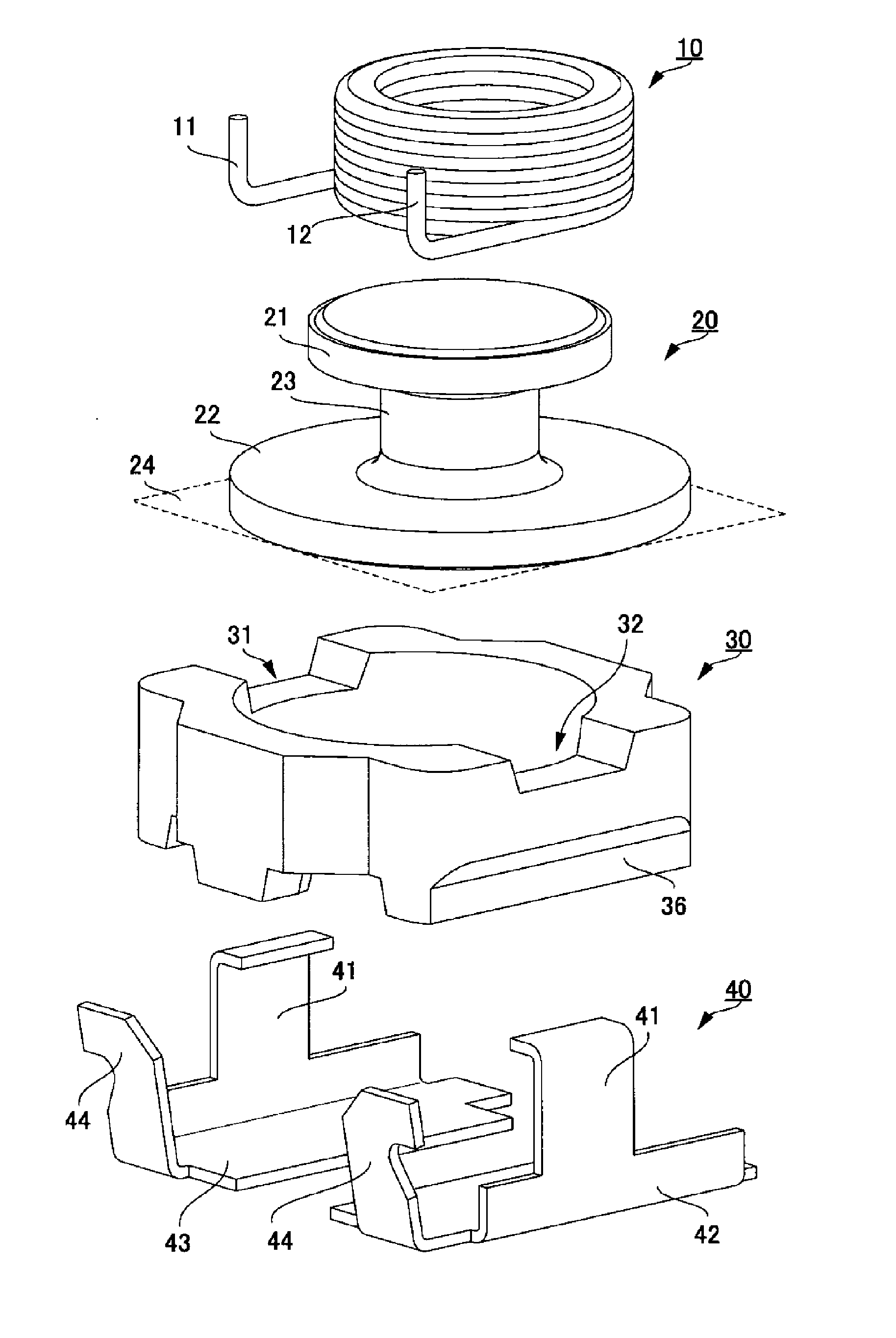
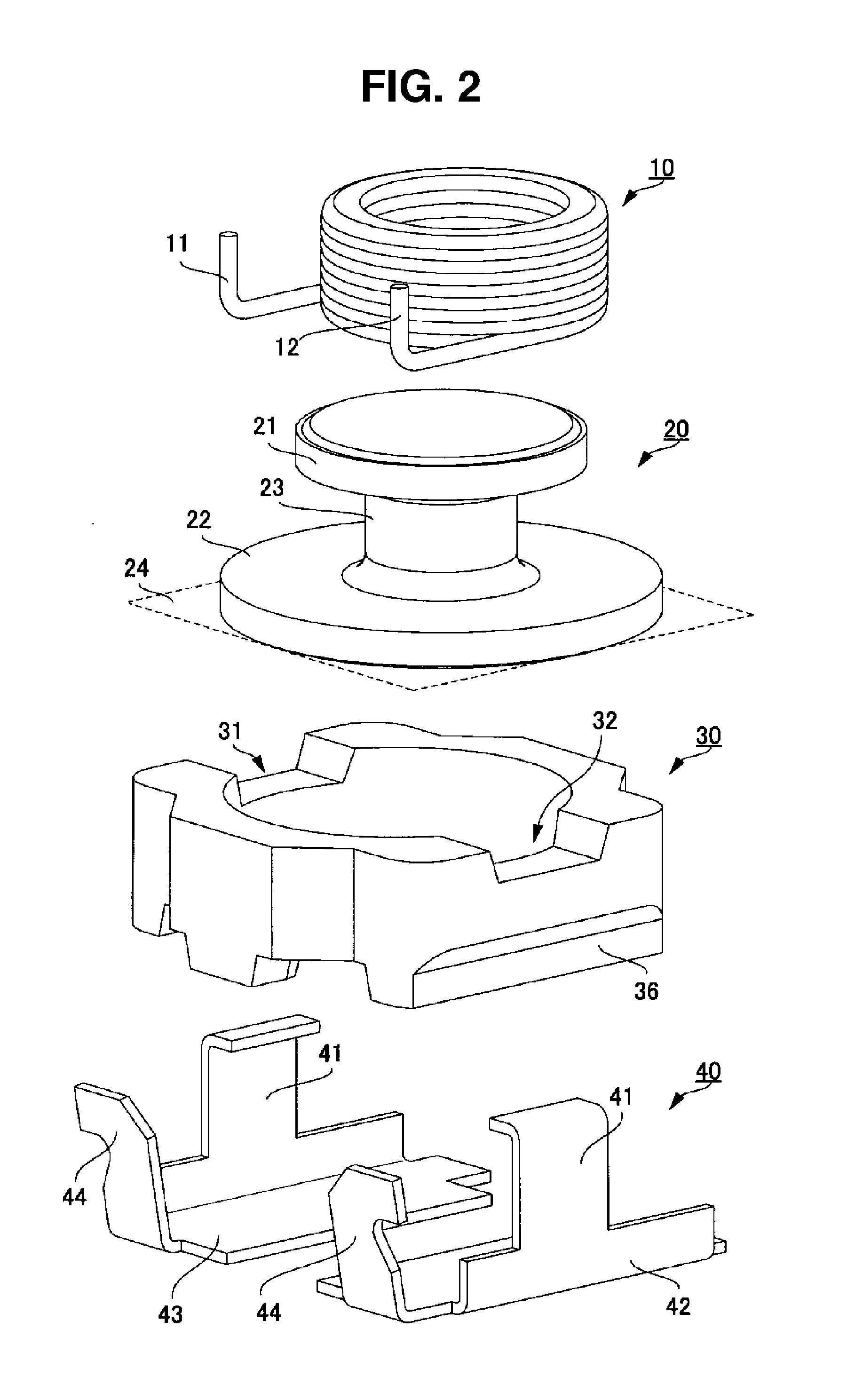
[0016]Hereinafter, it will be explained with respect to a first exemplified embodiment (hereinafter, referred to as “this embodiment”) of the present invention with reference to FIG. 1 to FIG. 5. In this exemplified embodiment, it will be explained with respect to an example in which the present invention is applied to a magnetic element 1 mounted on a mounting substrate which is not shown and which is provided on an electronic circuit of an automobile or the like to which vibration is added continuously.

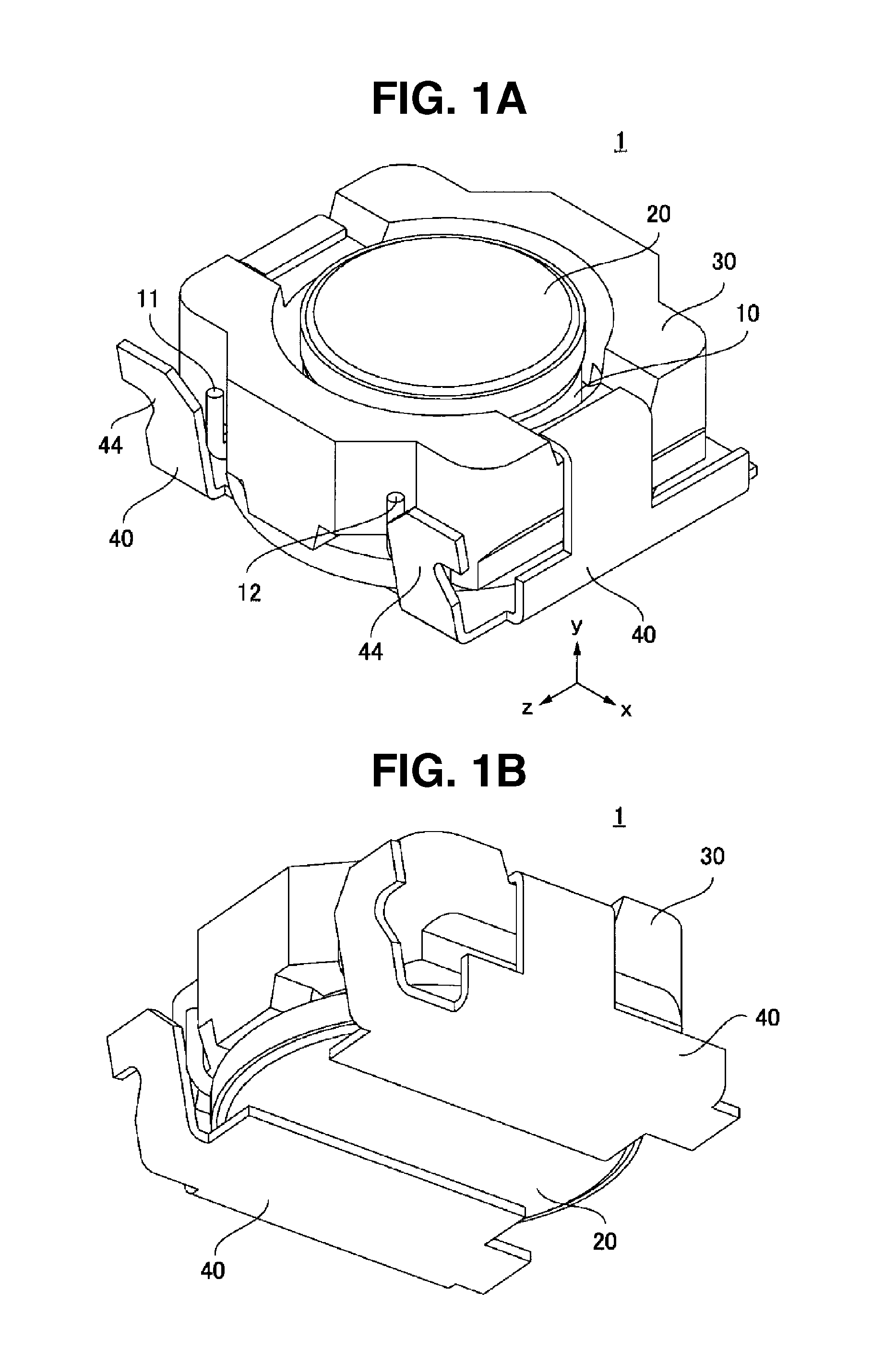
[0017]FIG. 1 is an outward-appearance perspective view showing a constitution example of the magnetic element 1 of this embodiment. FIG. 1A shows an example in which the magnetic element 1 is seen with respect to the upper surface thereof and FIG. 1B shows an example in which the magnetic element 1 is seen with respect to the bottom surface thereof.

[0018]The magnetic element 1 is provided with a first magnetic core 20, a coil 10 whose conductive wire i...

second exemplified embodiment

2. Second Exemplified Embodiment

[0051]Next, it will be explained with respect to a constitution of a magnetic element 70 relating to a second exemplified embodiment of the present invention. In this exemplified embodiment, the coil 10 is used as an air-core coil.

[0052]FIG. 6 is a perspective view showing a constitution example of the magnetic element 70.

[0053]The magnetic element 70 is constituted by the coil 10, a box shaped first magnetic core 71 whose one surface is opened, a plate shaped second magnetic core 72 which is fitted to the opened one surface of the first magnetic core 71, and metal terminals 74. Also, with respect to the magnetic element 70, the metal terminal is provided with a fixing portion 73 for fixing the second magnetic core 72, a solder fillet forming portion 75 which heightens the bonding strength when the magnetic element 70 is bonded onto a mounting substrate, and a mount portion 77 connected to the mounting substrate. Then, terminal ends extended from the ...


PUM


Abstract

A magnetic element including: a first magnetic core including a coil which is wound by a predetermined number of turns; a second magnetic core which includes the coil in the inside thereof and which is combined along the outer circumference of the first magnetic core; and a metal terminal which connects the coil and a mounting substrate, wherein the metal terminal includes a fixing portion for fixing the second magnetic core in a state of combining the first magnetic core and the second magnetic core.

Description

CROSS-REFERENCE TO RELATED APPLICATION[0001]This application claims priority to Japanese Utility Model Application No. JP U2011-4307 filed Jul. 25, 2011 which is hereby expressly incorporated by reference herein in its entirety.BACKGROUND[0002]1. Field of the Invention[0003]The present invention relates to a magnetic element which is mounted on an electronic circuit and makes it possible to maintain its performance even in such a circumstance vibration is added continuously.[0004]2. Description of the Related Art[0005]From the past, there has been used a magnetic element which is mounted on an electronic circuit installed in an automobile or the like and which adjusts impedance or the like. In a Patent Document 1 (Japanese unexamined patent publication No. 2010-205783), there is disclosed a general constitution relating to a magnetic element in the past. This magnetic element is provided with a coil, a ferrite drum core housing the coil in the inside thereof, a ring core housing the...

Claims


Application Information

Patent Timeline
IPC IPC(8): H01F27/24H01B5/02H01F27/29
CPCH01F27/292H01F17/04
Inventor URANO, YUICHIRO
Owner SUMIDA CORP
Features
  • Generate Ideas
  • Intellectual Property
  • Life Sciences
  • Materials
  • Tech Scout
  • Unparalleled Data Quality
  • Higher Quality Content
  • 60% Fewer Hallucinations
Learn More