Projector

a projector and projector technology, applied in the field of projectors, can solve the problems of difficult degradation of image resolution, achieve the effects of obtaining image display with preferable visibility, bright display, and high human luminosity factor

Active Publication Date: 2013-01-31
SEIKO EPSON CORP
View PDF3 Cites 24 Cited by
  • Summary
  • Abstract
  • Description
  • Claims
  • Application Information

AI Technical Summary

Benefits of technology

[0032]The third light, the fourth light, the fifth light, and the sixth light are different from each other in the light path length to the light modulation element. If the light path length to the light modulation element increases, the light enters the light modulation element in the state of being widely spread, and therefore, the light intensity of the light entering the display area of the light modulation element is lowered to thereby cause dark display. The third light is reflected by the first reflecting element and the third reflecting element, and therefore the light path length thereof to the light modulation element is the shortest. Therefore, the spread of the light is the narrowest, and bright display can be obtained. Therefore, by setting the third light to the green light or the yellow light with the higher human luminosity factor, image display with preferable visibility can be obtained.

Problems solved by technology

Therefore, the degradation of image resolution is difficult to occur.

Method used


Image

  • Projector
  • Projector
  • Projector

Examples


first embodiment

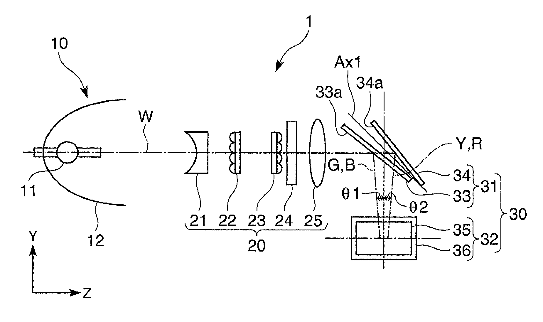
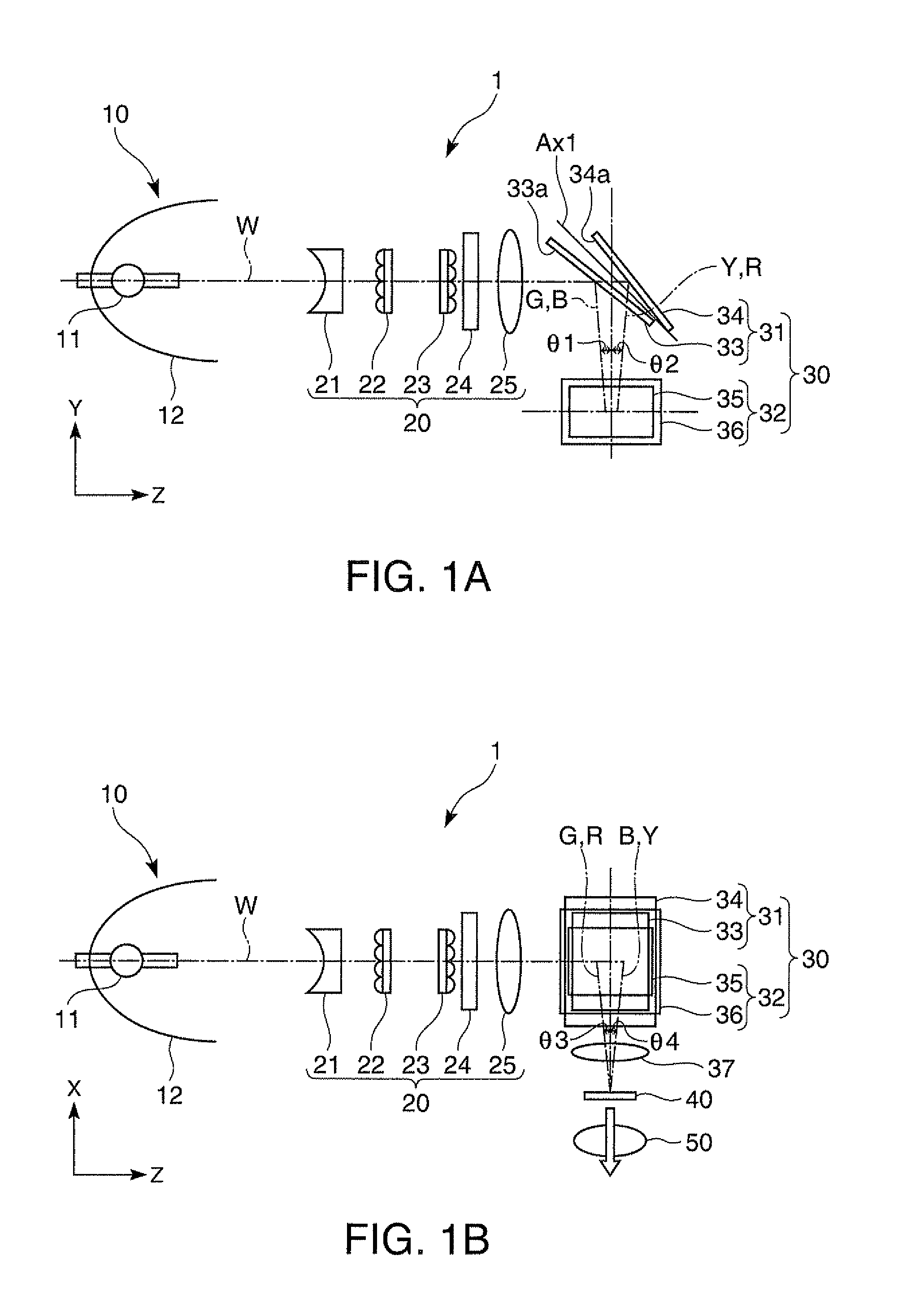
[0046]FIG. 1A is a side view of a projector 1 according to the first embodiment viewed from a horizontal direction, and FIG. 1B is a top view of the projector 1 viewed from a vertical direction.

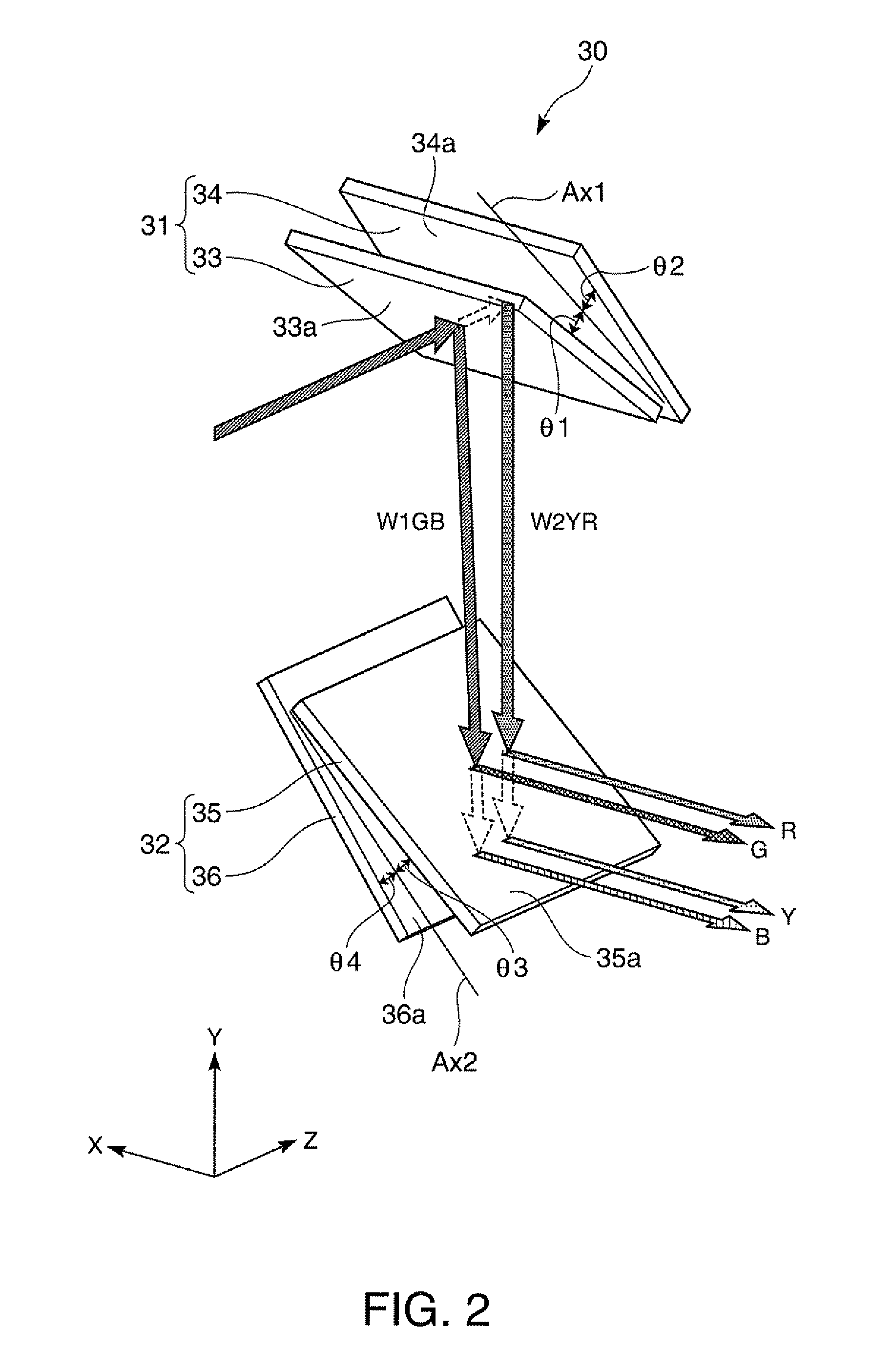
[0047]The projector 1 is provided with a light source 10 for emitting the non-polarized light W including the visible light, a polarization conversion optical system 20 for converting the light W emitted from the light source 10 into the light (e.g., the S-polarized light) with the polarization direction aligned, a light separation optical system 30 for separating the light W from the light source 10 into four types of colored light (third light G, fourth light B, fifth light R, and sixth light Y) in respective wavelength bands different from each other, a single light modulation element 40 for modulating the four types of colored light G, B, R, Y based on image information supplied from the outside to thereby form a color optical image, and a projection optical system 50 for projecting the c...

second embodiment

[0087]FIG. 5 is a schematic diagram of a light separation optical system 60 used in a projector according to a second embodiment. In the present embodiment, the constituents common to the present embodiment and the first embodiment are denoted by the same reference symbols, and the detailed explanation therefor will be omitted.

[0088]The point in which the light separation optical system 60 is different from the light separation optical system 30 according to the first embodiment is the point that the transmission wavelength and the reflection wavelength of the first reflecting element 63 and the third reflecting element 65 of the light separation optical system 60 are different from the transmission wavelength and the reflection wavelength of the first reflecting element 33 and the third reflecting element 35 of the light separation optical system 30 according to the first embodiment.

[0089]The first light separation optical system 61 includes the first reflecting element 63 for refl...

third embodiment

[0096]FIG. 7 is a schematic diagram of a light separation optical system 70 used in a projector according to a third embodiment. In the present embodiment, the constituents common to the present embodiment and the first embodiment are denoted by the same reference symbols, and the detailed explanation therefor will be omitted.

[0097]The point in which the light separation optical system 70 is different from the light separation optical system 30 according to the first embodiment is the point that the transmission wavelength and the reflection wavelength of the first reflecting element 73 and the third reflecting element 75 of the light separation optical system 70 are different from the transmission wavelength and the reflection wavelength of the first reflecting element 33 and the third reflecting element 35 of the light separation optical system 30 according to the first embodiment.

[0098]The first light separation optical system 71 includes the first reflecting element 73 for refle...


PUM


Abstract

A projector includes a light source, a first light separation optical system adapted to separate light emitted from the light source into first light and second light, a second light separation optical system adapted to separate the first light into third light and fourth light, separate the second light into fifth light and sixth light, and emit the third light, the fourth light, the fifth light, and the six light in directions intersecting with a plane including a light axis of the light emitted from the light source and a light axis of the first light, and a light modulation element which the third light, the fourth light, the fifth light, and the sixth light enter.

Description

BACKGROUND[0001]1. Technical Field[0002]The present invention relates to a projector.[0003]2. Related Art[0004]As a single-panel projector for performing color display by spatially separating the light emitted from a light source into a plurality of colored lights and then making the colored lights thus separated into respectively enter the corresponding sub-pixels, there is known a projector described in JP-A-4-60538 (Document 1). In the projector of Document 1, a red-light reflecting dichroic mirror, a green-light reflecting dichroic mirror, and a blue-light reflecting dichroic mirror are disposed along the incident light axis of the light emitted from the light source in a state nonparallel to each other. Thus, the light emitted from the light source is separated into red light, green light, and blue light having respective proceeding directions slightly different from each other on the same plane. The red light, the green light, and the blue light thus separated into are respect...

Claims


Application Information

Patent Timeline
Patent Type & Authority Applications(United States)
IPC IPC(8): G03B21/28G03B21/14
CPCG02B27/102G02B27/141H04N9/3108G03B33/04G03B33/06G03B21/2066
Inventor AKIYAMA, KOICHIHASHIZUME, TOSHIAKI
Owner SEIKO EPSON CORP
Why Eureka
Try Eureka