
MDCT-Based Complex Prediction Stereo Coding

a complex prediction and stereo coding technology, applied in the field of stereo audio coding, can solve the problems of not optimizing for higher bit rate computational complexity, not improving coding efficiency, and typically not using sbr tools, and achieve the effect of computational efficiency

Active Publication Date: 2013-01-31
DOLBY INT AB
View PDF4 Cites 64 Cited by
  • Summary
  • Abstract
  • Description
  • Claims
  • Application Information

AI Technical Summary

Benefits of technology

The present invention provides methods and apparatus for stereo coding that are computationally efficient even at high bitrates. The invention benefits from the advantages of unified stereo coding in the MPEG USAC system. The critically sampled MDCT transform, which is the basis of the MPEG USAC transform coding system, can be used for complex prediction stereo coding as provided by the invention, at least in cases where the code audio bandwidths of the downmix and residual channels are the same and the upmix process does not include decorrelation. The use of TNS increases the perceived audio quality for signals with transient-like components. The decoder system includes at least one temporal noise shaping module which increases the perceived audio quality for signals with transient-like components. The invention provides efficient coding at high bitrates and allows for a level of quality at least equivalent to that of direct or joint coding. The complex prediction coefficient is determined to reduce or minimize the signal power or average signal power of the residual signal.

Problems solved by technology

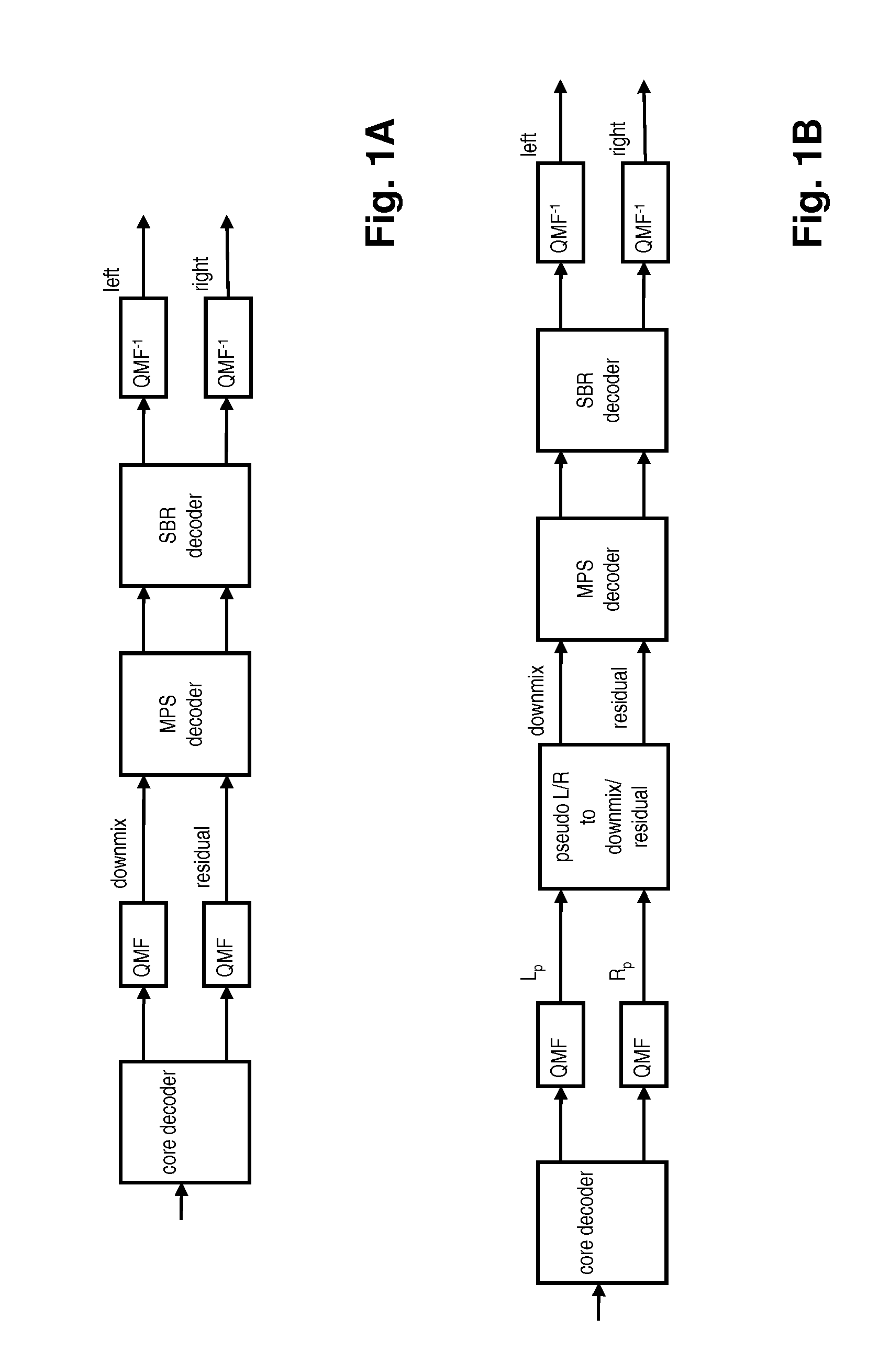
The above coding structure is well suited for low bit rates, typically below 80 kb / s, but is not optimal for higher bit rates with respect to computational complexity.
More precisely, at higher bitrates, the SBR tool is typically not utilized (as it would not improve coding efficiency).
Then, in a decoder without a SBR stage, only the complex-valued upmix matrix motivates the presence of the QMF filter bank, which is computationally demanding and introduces a delay (at a frame length of 1024 samples, the QMF analysis / synthesis filter bank introduces a delay of 961 samples).

Method used


Image

  • MDCT-Based Complex Prediction Stereo Coding
  • MDCT-Based Complex Prediction Stereo Coding
  • MDCT-Based Complex Prediction Stereo Coding

Examples


Embodiment Construction

I. Decoder Systems

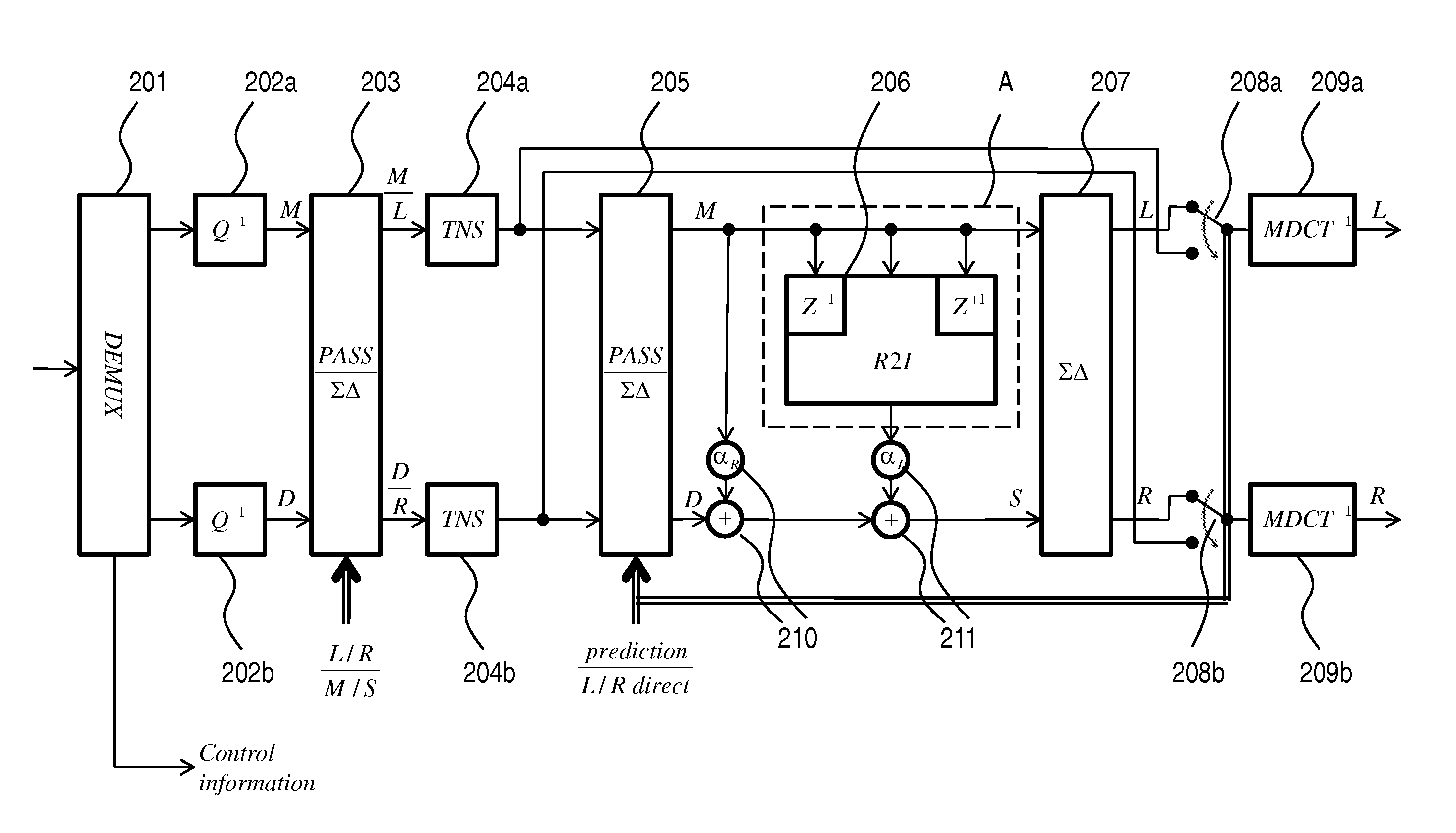
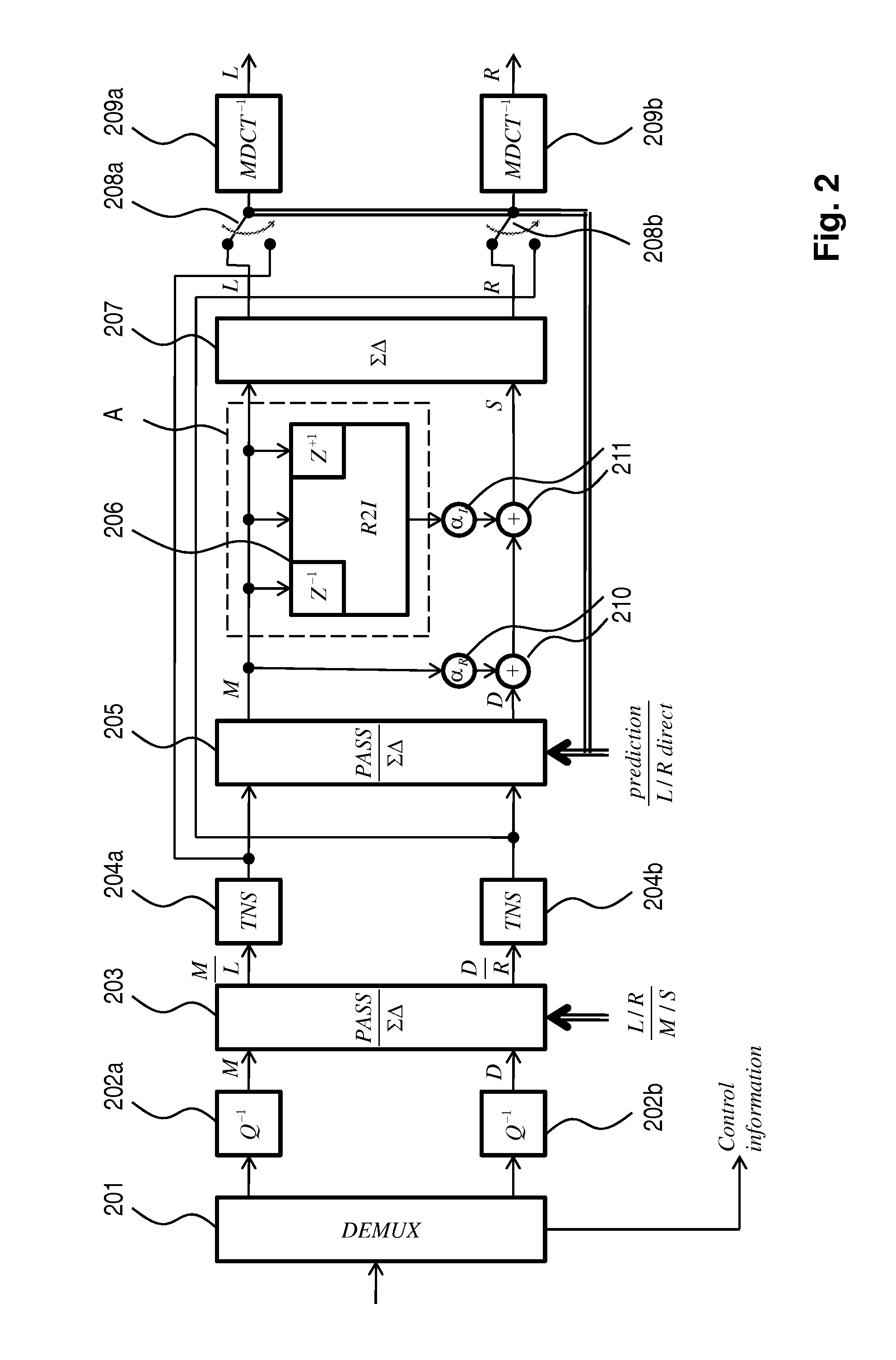
[0082]FIG. 2 shows, in the form of a generalized block diagram, a decoding system for decoding a bit stream comprising at least one value of a complex prediction coefficient α=αR+iαI and an MDCT representation of a stereo signal having downmix M and residual D channels. The real and imaginary parts αR, αI of the prediction coefficient may have been quantized and / or coded jointly. Preferably however, the real and imaginary parts are quantized independently and uniformly, typically with a step size of 0.1 (dimensionless number). The frequency-band resolution used for the complex prediction coefficient is not necessarily the same as the resolution for scale factors bands (sfb; i.e., a group of MDCT lines that are using the same MDCT quantization step size and quantization range) according to the MPEG standard. In particular, the frequency-band resolution for the prediction coefficient may be one that is psycho-acoustically justified, such as the Bark scale. A demultip...


PUM


Abstract

The invention provides methods and devices for stereo encoding and decoding using complex prediction in the frequency domain. In one embodiment, a decoding method, for obtaining an output stereo signal from an input stereo signal encoded by complex prediction coding and comprising first frequency-domain representations of two input channels, comprises the upmixing steps of: (i) computing a second frequency-domain representation of a first input channel; and (ii) computing an output channel on the basis of the first and second frequency-domain representations of the first input channel, the first frequency-domain representation of the second input channel and a complex prediction coefficient. The upmixing can be suspended responsive to control data.

Description

TECHNICAL FIELD[0001]The invention disclosed herein generally relates to stereo audio coding and more precisely to techniques for stereo coding using complex prediction in the frequency domain.BACKGROUND OF THE INVENTION[0002]Joint coding of the left (L) and right (R) channels of a stereo signal enables more efficient coding compared to independent coding of L and R. A common approach for joint stereo coding is mid / side (M / S) coding. Here, a mid (M) signal is formed by adding the L and R signals, e.g. the M signal may have the formM=(L+R) / 2Also, a side (S) signal is formed by subtracting the two channels L and R, e.g., the S signal may have the formS=(L−R) / 2In the case of M / S coding, the M and S signals are coded instead of the L and R signals.[0003]In the MPEG (Moving Picture Experts Group) AAC (Advanced Audio Coding) standard (see standard document ISO / IEC 13818-7), L / R stereo coding and M / S stereo coding can be chosen in a time-variant and frequency-variant manner. Thus, the ster...

Claims


Application Information

Patent Timeline
Patent Type & Authority Applications(United States)
IPC IPC(8): H04R5/00G10L19/008
CPCG10L19/008G10L25/12G10L19/0212G10L19/18G06F3/162G10L19/06G10L19/167H04S3/008H04S2400/01G10L19/002G10L19/022G01L19/00G10L19/012G10L19/03
Inventor PURNHAGEN, HEIKOCARLSSON, PONTUSVILLEMOES, LARS
Owner DOLBY INT AB
Learn More