Axial-radial turbomachine

a turbomachine and axial-radial technology, applied in the direction of motors, liquid fuel engines, non-positive displacement pumps, etc., can solve the problems of increasing the thickness of the wall, increasing the material cost and the weight of the axial-radial flow machine, and achieve the effect of small wall thickness

Inactive Publication Date: 2013-01-31
MAN ENERGY SOLUTIONS SA
View PDF4 Cites 2 Cited by
  • Summary
  • Abstract
  • Description
  • Claims
  • Application Information

AI Technical Summary

Benefits of technology

[0009]It is an object of one embodiment of the invention to provide an axial-radial flow machine in which the dividing wall is reliably prot...

Problems solved by technology

It can easily be seen that a wall thickness increased in this way consider...

Method used


Image

  • Axial-radial turbomachine
  • Axial-radial turbomachine
  • Axial-radial turbomachine

Examples


Embodiment Construction

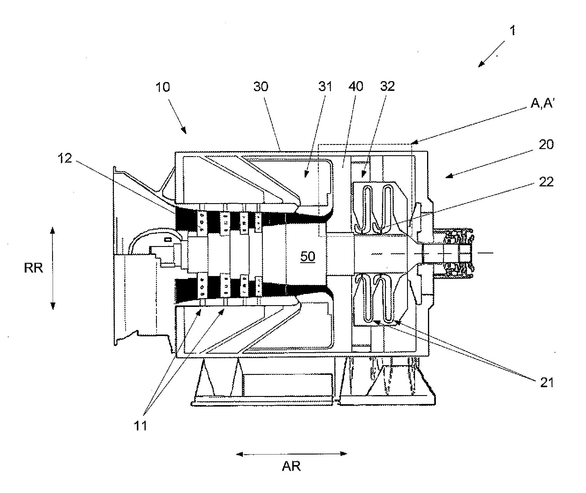
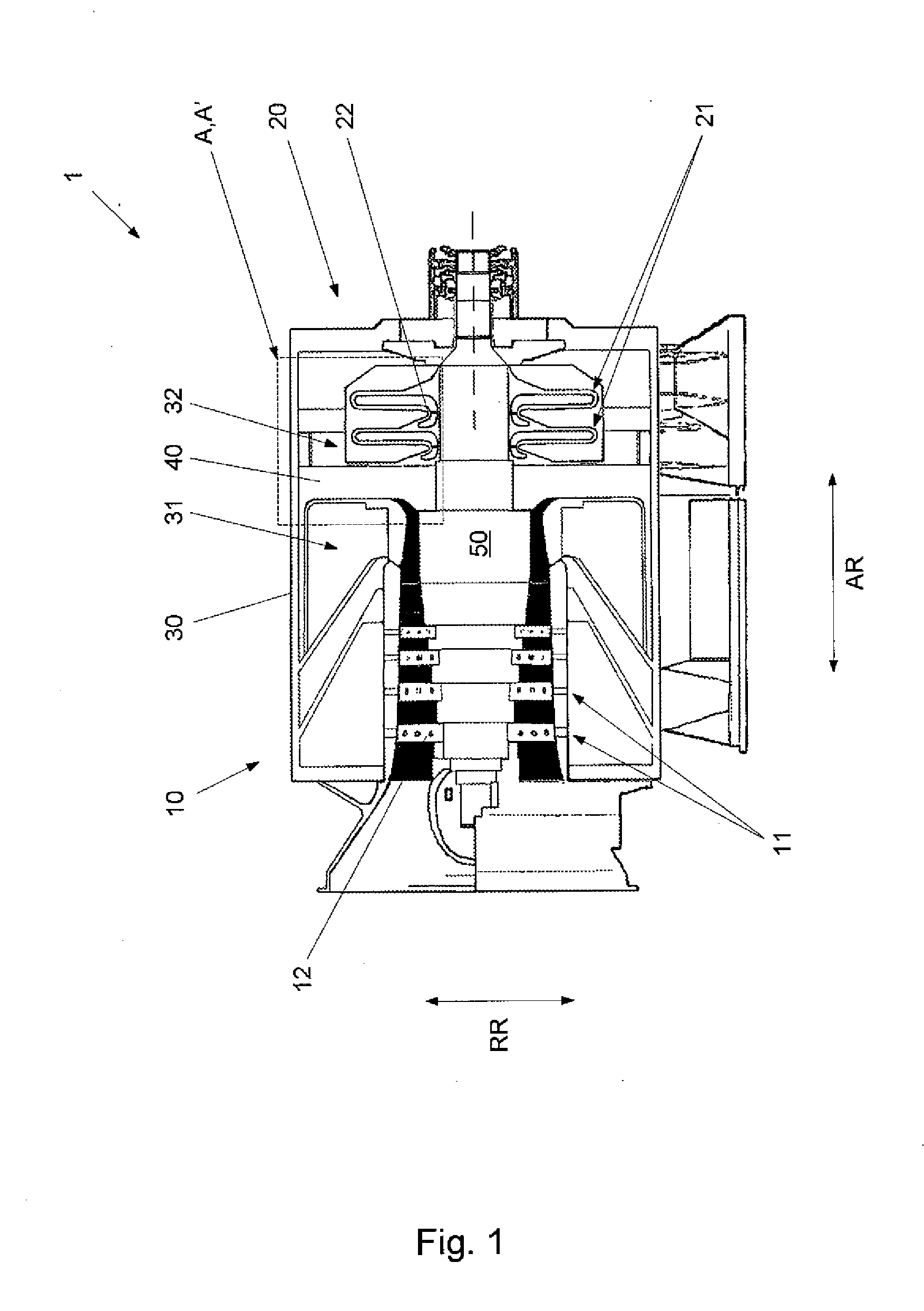
[0036]An axial-radial flow machine 1 according to an embodiment form of the invention will be described in the following with reference to FIG. 1 and FIGS. 3 to 6. According to one embodiment of the invention, the axial-radial flow machine 1 is formed by an axial-radial compressor (a compressor having an axial compressor and a radial compressor assembled to form a constructional unit).

[0037]The axial-radial flow machine 1 according to the invention has an axial portion 10 including a plurality of axial stages 11, a radial portion 20 including a plurality of radial stages 21, a housing 30 having an interior space which, by a dividing wall 40′ extending in a radial direction RR of the housing 30, is divided in an axial direction AR of the housing 30 into a first partial space 31 in which the axial portion 10 is received and a second partial space 32 in which the radial portion 20 is received, and a shaft 50 which extends in axial direction AR through the interior space of the housing ...


PUM


Abstract

Axial-radial flow machine having an axial portion with at least one axial stage, a radial portion with at least one radial stage, a housing having an interior space with a dividing wall extending in a radial direction dividing the housing in an axial direction into a first partial space in which the axial portion is received and a second partial space in which the radial portion is received, and a shaft that extends in axial direction through the interior space and through the dividing wall and on which impellers of the axial portion and of the radial portion are received. A radial gap is formed between the dividing wall and a fluid guiding element of the radial portion. The fluid guiding element is axially fixed to the housing so as to be adjacent to the dividing wall. A plurality of fixing units which are distributed in circumferential direction are arranged in the radial gap, each of which fixing units axially fixes the dividing wall to the fluid guiding element.

Description

CROSS REFERENCE TO RELATED APPLICATION[0001]This is a U.S. national stage of application No. PCT / DE2010 / 050030, filed on 25 May 2010. Priority is claimed on German, Application No. 10 2009 029 647.6, filed 21 Sep. 2009, the content of which is incorporated here by reference.BACKGROUND OF THE INVENTION[0002]1. Field of the Invention[0003]The invention is directed to an axial-radial flow machine having an axial portion including at least one axial stage and a radial portion including at least one radial stage.[0004]2. Detailed Description of Prior Art[0005]An axial-radial flow machine I as that shown in FIG. 1 has an axial portion 10 including a plurality of axial stages 11, a radial portion 20 including a plurality of radial stages 21, a housing 30 having an interior space which, by a dividing wall 40 extending in a radial direction RR of the housing 30, is divided in an axial direction AR of the housing 30 into a first partial space 31 in which the axial portion 10 is received and a...

Claims


Application Information

Patent Timeline
IPC IPC(8): F01D1/02
CPCF01D25/243F04D25/16F04D17/025F04D17/122
Inventor LANGE, CHRISTOPHRICHTER, ARNO
Owner MAN ENERGY SOLUTIONS SA
Why Eureka
Try Eureka